| Week 07 AutoCAD 2013 | |
|---|---|
| Course | Arch 100b |
| Date | 2014/02/28 |
| Learning Objectives | This workshop will give you an intermediate introduction to AutoCAD 2013. The topics encompassed will include how to manage layer properties, external references and plotting. |
| Agenda |
|
| Uses Tool(s) | [[AutoCAD 2013|]] |
LAYER MANAGEMENT
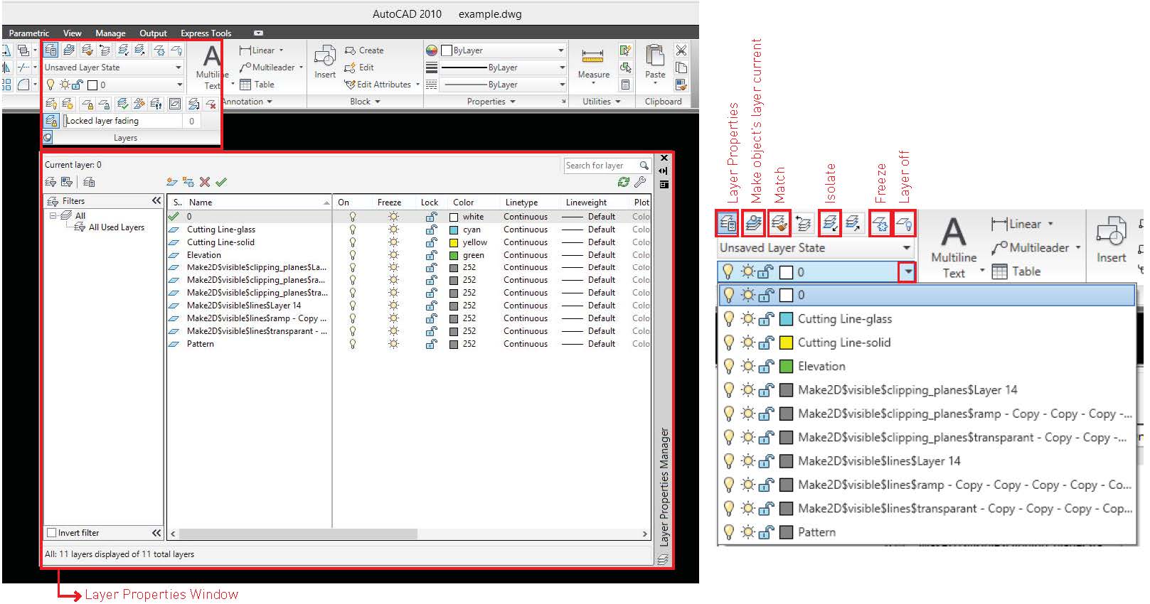
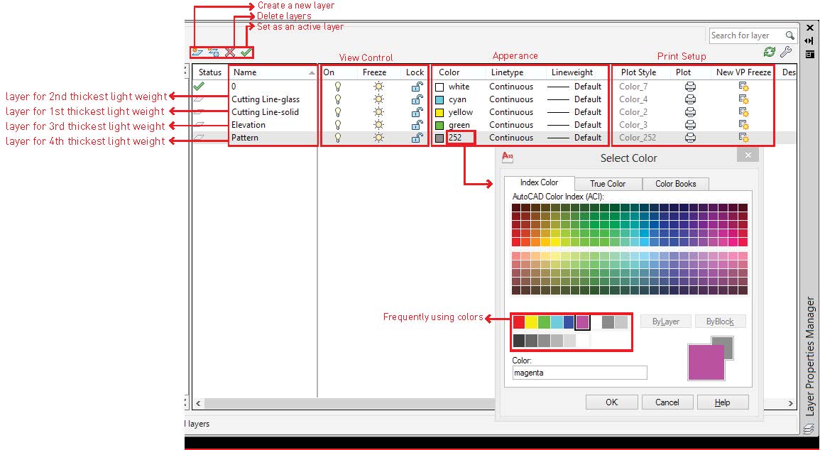
AutoCAD Layers are an integral part of working and it is crucial to stay organized for efficient workflow. To open the “Layer Properties” win¬dow click on far left icon in the Layers Panel. The “Layer Properties” allows for the addition of new layers, changing of layer properties (color, line-weight, and line-type). “New Layer” creates an additional layer. “New Layer VP Frozen” creates a new layer but is not visible when printed on paper-space. “Delete Layer” removes the selected later. “Set Current Layer” allows the selected layer to be edited in the model space. To change the color of a specific layer, double click on the box which aligns with the desired layer which will then prompt a color selection. To change line-type or line-weight, double-click on the respective layer. To switch objects into another layer, simply select all objects and click the desired layer.
The convenient way to set up layers is to create layers by the different line weights you need. For example, cutting line would need to be shown thicker that other lines behind it, and patterns or hatches would be shown with the thinnest line weight due to the density.
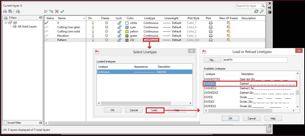
There are many kinds of default linetype in AutoCAD than Rhino. By using different linetypes, you can express clear and well hierachy drawing. To add linetype, click “Load” under the linetype option and select the type you want to add.
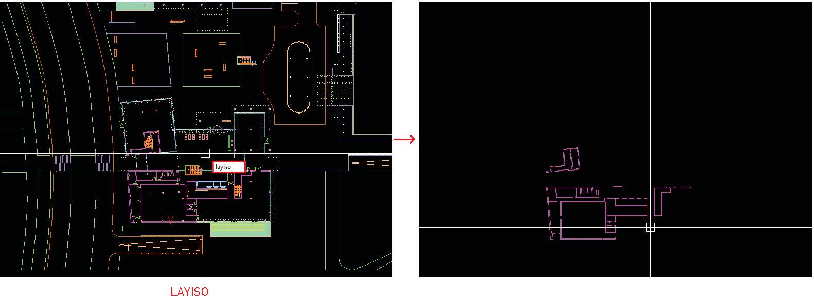 Comment “Layiso” helps when you only need one layer turned on to modify.
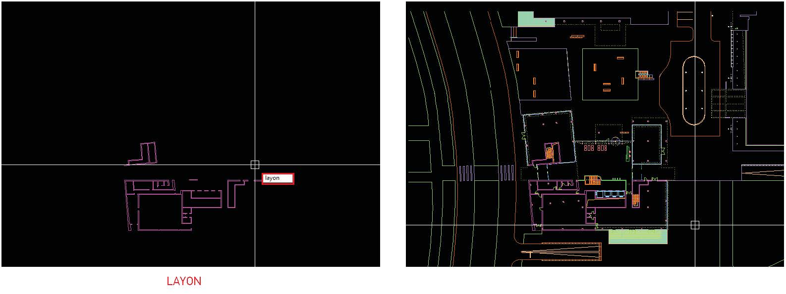 Comment “Layon” helps to turn on all layers. When the layers are freezed, they aren’t shown even though you turn on all layers.
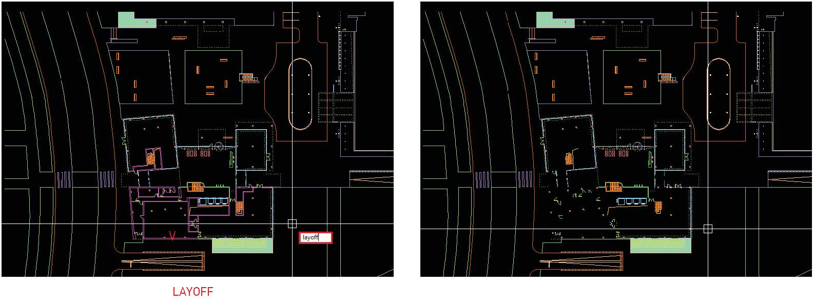 Comment “Layoff” helps when you only need one layer turned off to modify.
EXTERNAL REFERENCE
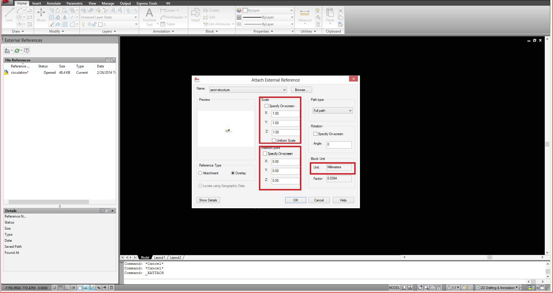
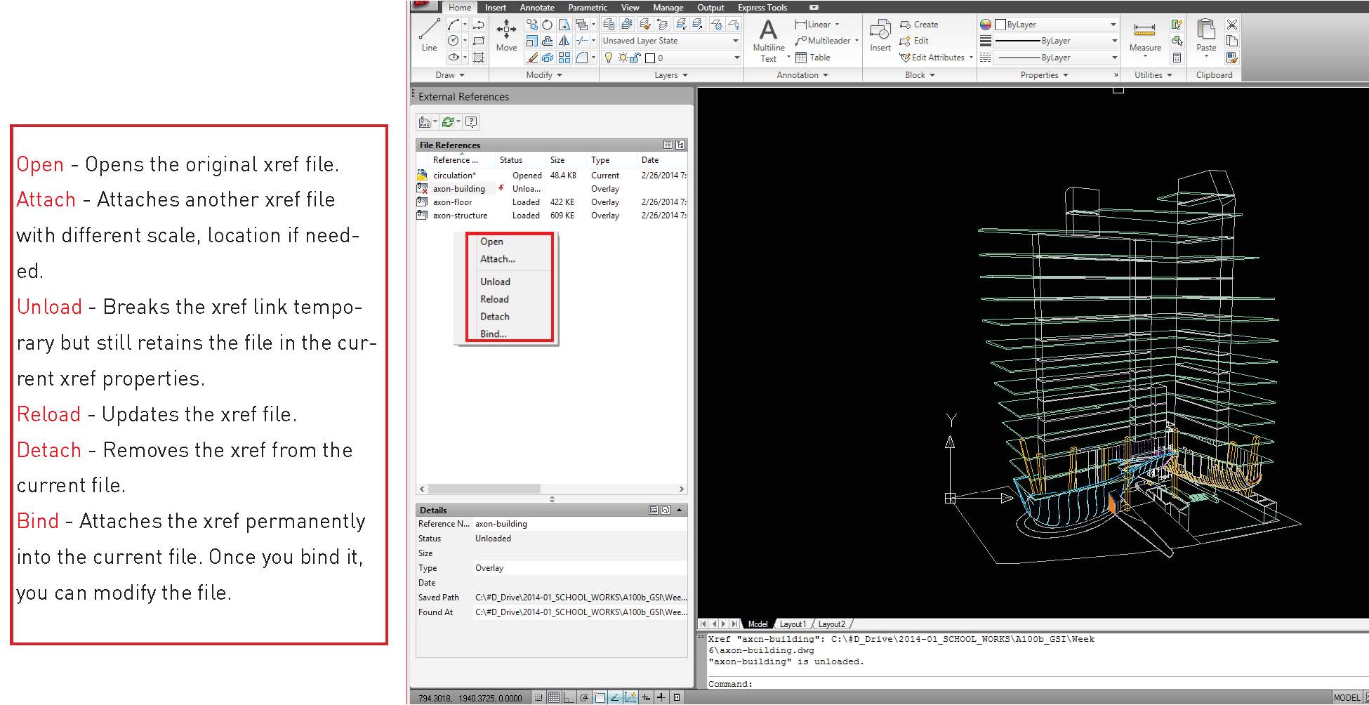
XREF allows to link other dwg files or images into the current file without attaching it, so once you revise other files, they are automatically up¬dated to your current file. Type “xref” in command bar, then select files that you want to link with.
When you open xref file, it asks you about size, unit and location of the xref file. If you are working multiple stories building, and it has a plan drawing on each file, you would want to see the overlaid plans so that you can clearly match all plans. In this example, the first plan of building is opened to draw the second plan.
The basic setup for transparency of xref drawing meant to clearly distinguish xref drawing form original drawing. However, if the default xref drawing looks too dark to read, go to xref setting display on options for your preference.
If you want to edit xref drawing, one way is to open the original xref drawing file and update it on current file after modifi cation.
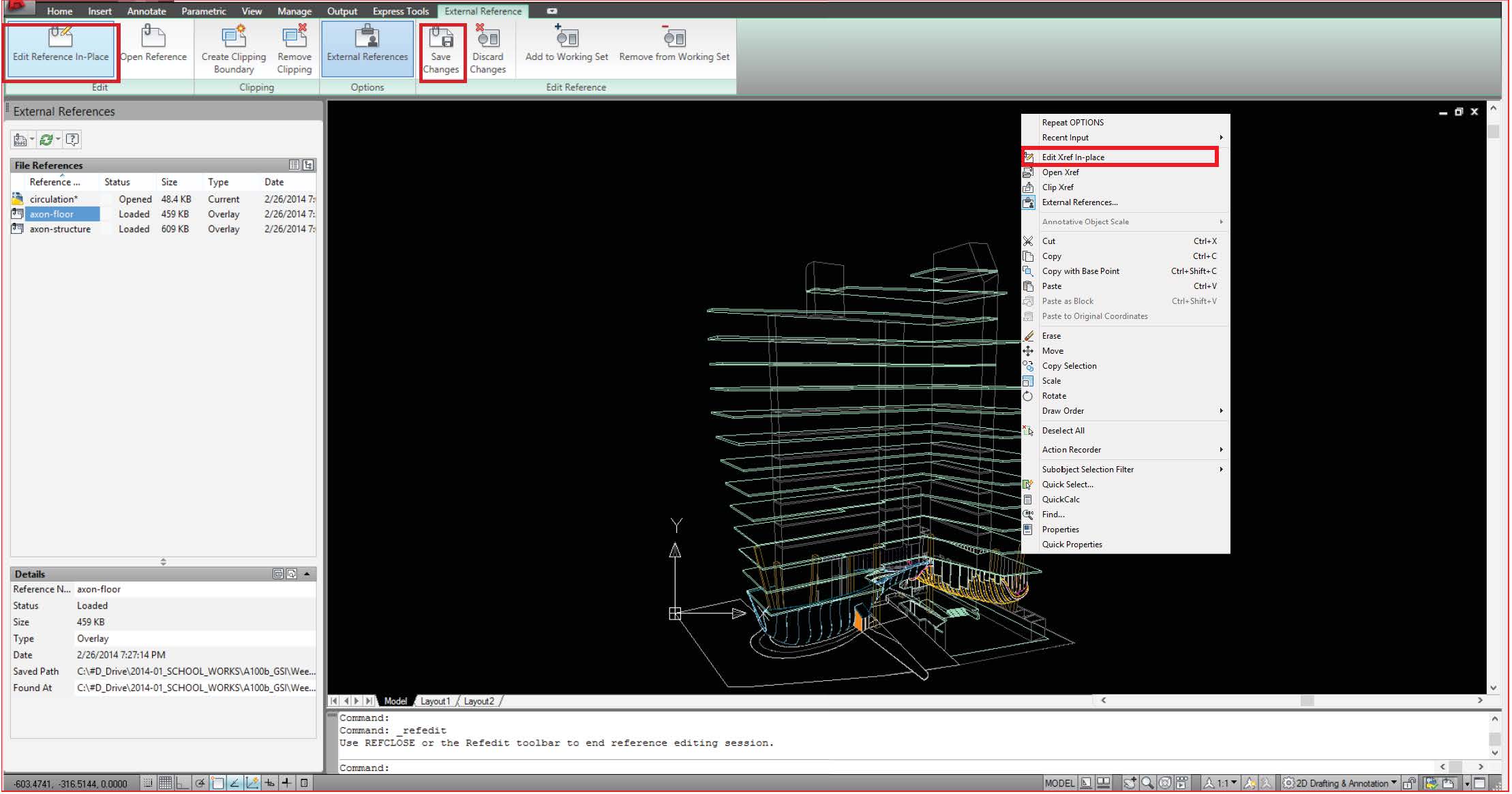
If you want to edit xref drawing in the current file, you can select the referenced object that you want to modify, right-click and click “Edit Xref In-Place” to edit in current file. In this case, you will not see the alert message although the file is updated.
PLOT MANAGEMENT
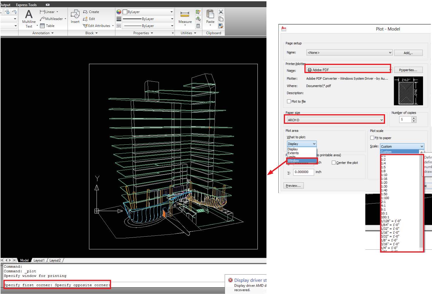
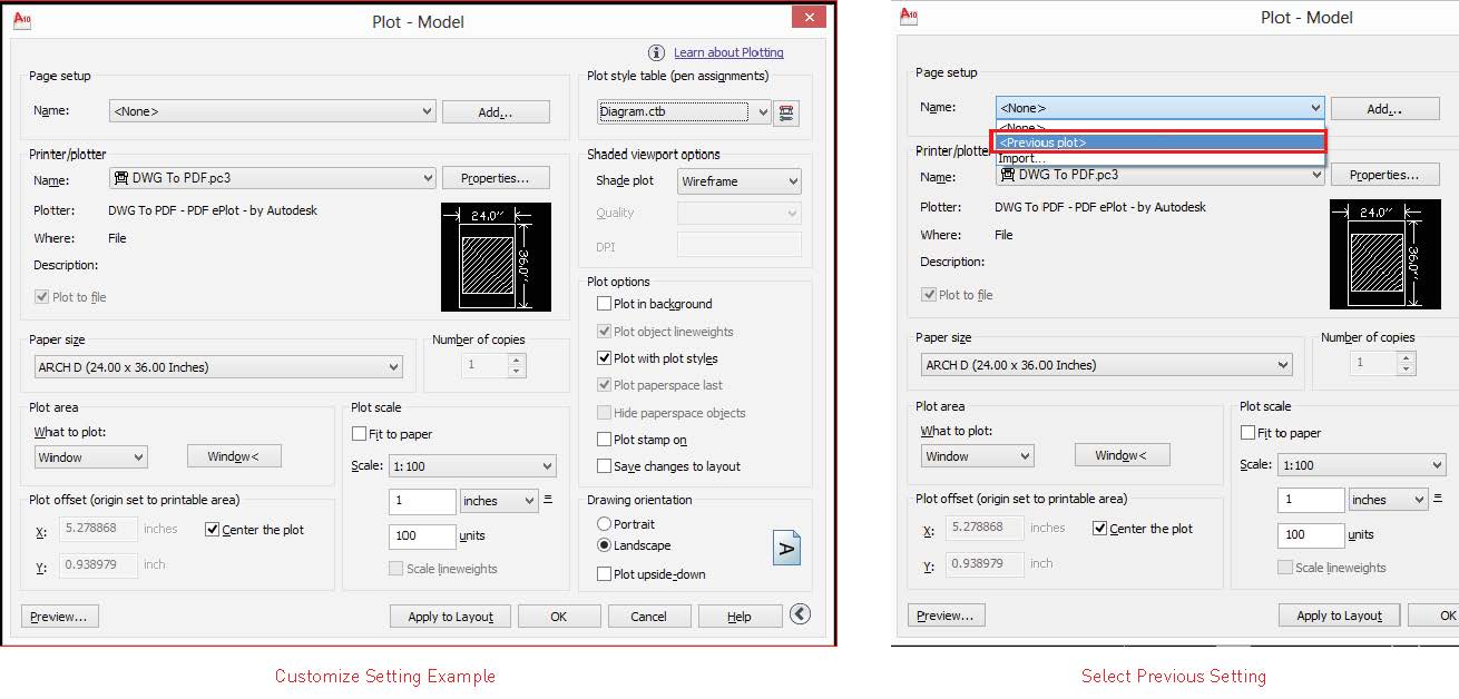
AutoCAD plotting/ printing system is a lot beneficial when you need to print same layout or setting with multiple files. And, once you customize line color, type and weight by your own setting and save it, you can apply it to all drawings you produce. To open plotting option, type "plot" or ctrl+p.
Select printer type, paper size and plot scale by scrolling. To determine the area where to print, select "window" under what to plot section, and create a boundary on workspace.
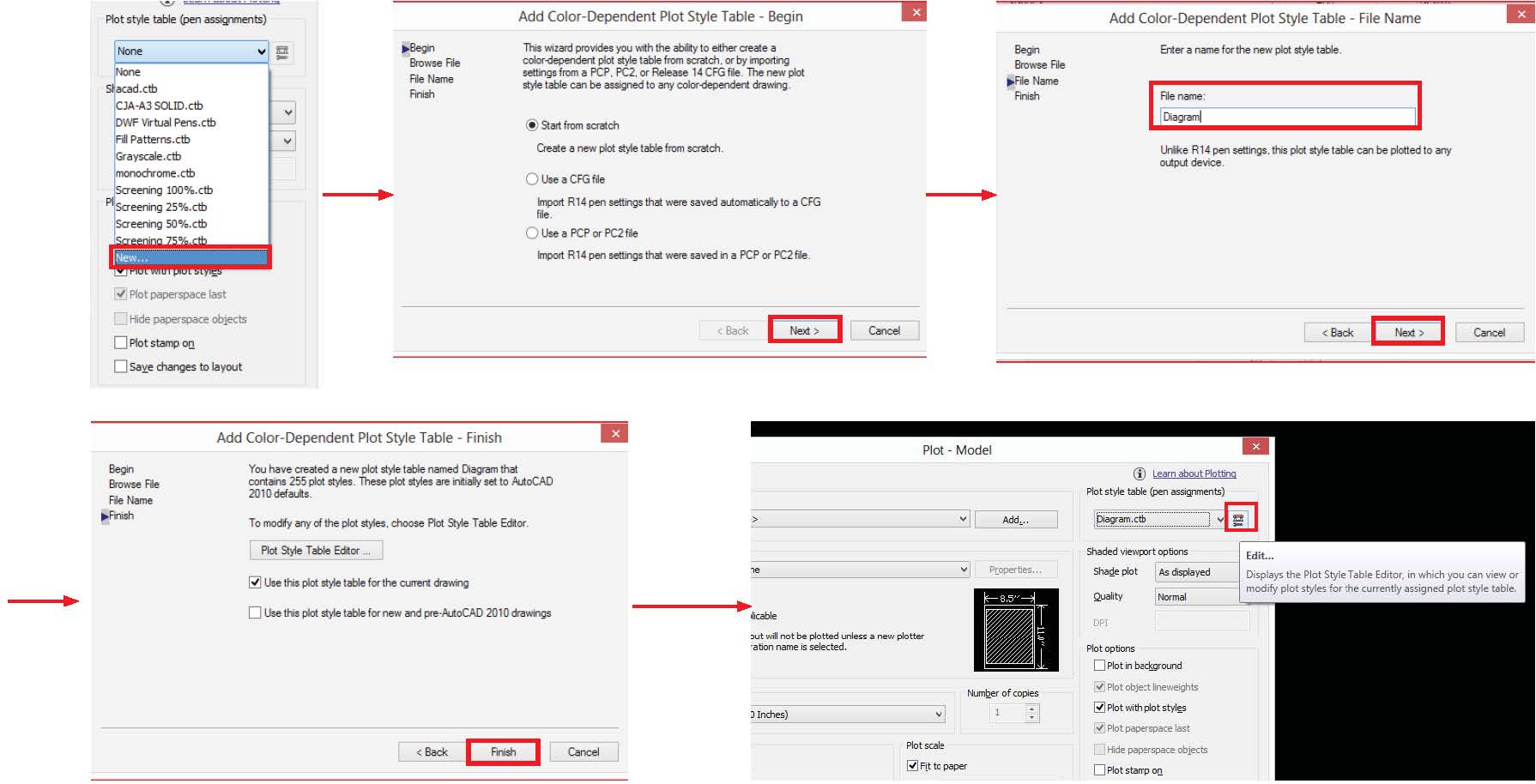
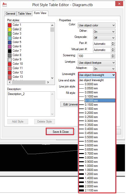
There is a sub file (.ctb) under AutoCAD program folder which includes the customize line style that you can use everytime you plot with AutoCAD. To create new ctb file, select "New" under Plot style table. Once you create your own ctb file, select it and click "edit". You can edit line styles by selecting individual plot styles. Normally, line type is set by layer, so only change line weight on ctb file.
In future, if you want to go back to your previous plotting setting, select <previous plot> under page setup.
