| Week 02_ AutoCAD 2013 | |
|---|---|
| Course | Arch 100b |
| Date | 2014/01/31 |
| Learning Objectives | This tutorial is geared toward the beginner and will give an in-depth introduction to AutoCAD 2013. The topics encompassed will include starting a new document, describing and using tools, using layers to efficiently draw, etc. The tutorial is meant only to skim the surface allowing the new user to familiarize with the program. Although there are many ways to draw in AutoCAD and everyone has their own personal preference, these steps and guides will provide a good foundation for using the program. |
| Agenda |
|
| Uses Tool(s) | [[AutoCAD 2013|]] |

1. Go to the Autodesk website (www.autodesk.com) and click the “Communities” tab. Within this tab, select “Students and Educators” and will load a new page. To the right of the webpage, select “Create a New Account”. Log-in information will be needed to download software. After registering, go back to the Student and Educator page and select “College and University”. Here, there will be a list of programs available for download. Select “AutoCAD”. This would also be a good opportunity to download Revit or 3D Max.

1.2 After the download they will ask for an Activation Code which will be available within the student profile that was previously created. For more help with download and activation please visit: http://usa.autodesk.com/adsk/servlet/ps/dl/item?siteID=123112&id=17971157&linkID=9240617

2. The default layout of AutoCAD when first opened will be “Drafting and Annotation”. This can be changed with the dropdown menu to “Classic”, which some people who have used AutoCAD before are familiar with. HOWEVER, this tutorial will be run in “Drafting and Annotation”. The advantage of “Drafting and Annotation” is that similar tools are grouped into the same category (i.e. drawing tools, modifying tools, measuring tools, etc.). The large “A” in the top left corner houses operational commands such as save, print, export, and UNITS. Always make sure that the Units are correct before starting a drawing.

3. To Create a New Drawing, Click the “A” at the top left corner and select new. At this point, a template selection screen will appear. Select “acad”. Of course, a template can be created with pre-set line weights, line types, etc.

4. Units are an integral part of AutoCAD. Make sure that before starting a drawing the desired units are set. This will prevent having to scale everything at the end, which is possible, but can often lead to error. Always draw at a 1:1 scale.

5. Layers are an integral part of working in AutoCAD and it is crucial to stay organized for efficient workflow. To open the “Layer Properties” window click on far left icon in the Layers Panel. The “Layer Properties” allows for the addition of new layers, changing of layer properties (color, line-weight, and line-type). “New Layer” creates an additional layer. “New Layer VP Frozen” creates a new layer but is not visible when printed on paper-space. “Delete Layer” removes the selected later. “Set Current Layer” allows the selected layer to be edited in the model space. To change the color of a specific layer, double click on the box which aligns with the desired layer which will then prompt a color selection. To change line-type or line-weight, double-click on the respective layer. To switch objects into another layer, simply select all objects and click the desired layer in dropdown menu.
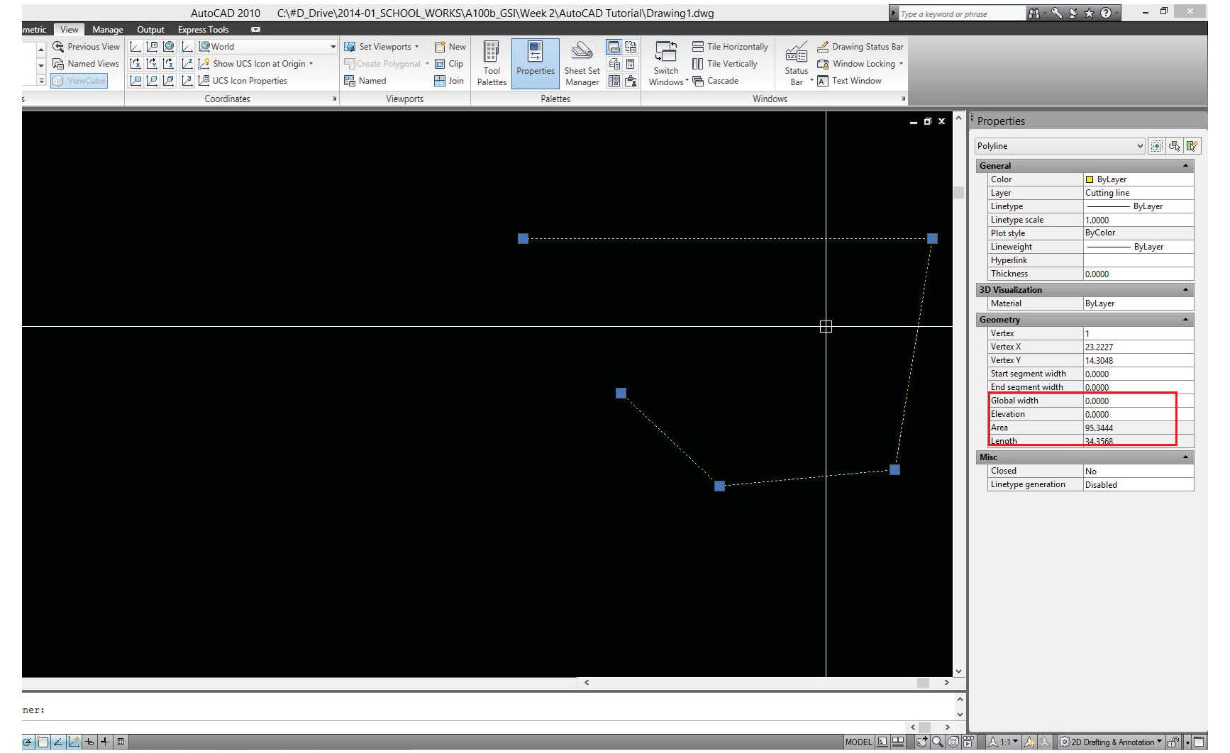

6. Line properties can show the specific line-type and weight of chosen lines. When a line is chosen, right-click and select "Properties" If a closed polyline, rectangle, or circle is selected, the area measurement is also available.

7. In options, many attributes of the AutoCAD interface can be changed to fit specific preferences.

8. Snaps extremely useful in creating clean drawings without gaps or crooked lines. Snaps allow objects to easily attach to an edge of another object or allow lines to be drawn completely orthogonal. An important tool within this menu is "Dynamic Imput" which gives the length and angle of a line when drawing. Here a specific measurement or angle can also be input.
9.

• Line – creates straight line segments: left click to set first point, drag mouse to desired length/angle, or type dimension, left click again.
• Polyline – a sequence of lines created as a single planar object: left click to set first point, drag mouse to desired length/angle, or type dimension, hit space for enter to finish command.
• Offset – creates a line offset a specific distance from original line: select object to offset, click desired edge to offset from, drag mouse towards direction of desired offset.
• Array – distributes object copies in rows and columns in specific dimensions: select object for array. When in command the top tool bar will change allowing to change the number of repeats in the x and y direction as well as the distances between.
• Copy – creates a duplicate object: select object to copy at the point of desired snapping (i.e. the center, the edge, or calculated point in line). Click to duplicate as many times, hit enter or space to exit command.
• Move – moves object specific distance: select object, drag mouse or type distance of move, click to place.
• Trim – trims objects to meet edges of another: select the line that trims the others. Click lines on the side of desired trim.
• Fillet – rounds edges of objects: enter command, type "R" to set radius, select first corner, select second corner, hit enter or space to exit command.
• Extend – extends objects to meet edges of another: select reference line for extend, hit enter, select lines wishing to extend.
• Circle – creates a circle of a specific dimension: click to set center of circle, drag mouse or type specified length, click again.
• Join – combines two objects into one segment: select all objects to join, hit enter. Remember, only works with lines that intersect.
• Explode – breaks objects into separate segments: select objects to explode, hit enter. Only works on poly-lines.
• Group – allows a group of objects to be selected without joining into one segment: select objects to group, hit enter. Allows the selection of the entire group by only selecting one object.
• Ungroup – ungroups grouped objects: click grouped object and hit enter.
• Scale – change size of objects without compromising proportions: draw line of desired length, snap line to corresponding object, select all objects to scale, select point at which the drawn line and selected line meet, drag mouse to reach edge of drawn line to scale.
• Dist – defines dimensions of object: click one edge of object, click other edge. Distance will show up in task bar.
• Arc – creates arc using 3 points: click to set first point, click to set second point, then set desired angle, click to complete command.
• Rotate – rotates objects in specific angle: Select point of rotate, drag mouse until at the desired angle.
• Mirror – flips image on given plane: select object to reflect, select point of reflection, drag mouse to mirror, hit enter to finish.
• Layon – turns layers on: select line in desired layer to turn on, hit enter.
• Layoff – turns layers off: select line in desired layer to turn off, hit enter.
• Layiso – isolates selected layers: select line in desired layer to isolate, hit enter.
• Object snap – allows the snapping of objects to edges of other objects
• Ortho – only allows drawing and movement in an orthogonal plane
• Grid – toggles grid off and on in drawing space
• Zoom extend – zooms to fit model in drawing space
• Dynamic input- displays length and angle beneath drawn line
• XRef - much like InDesign, it allows the placing of other AutoCAD files into the current file. This is useful for creating layouts and also referencing multiple floors with similar characteristics. Enter command, select file, and click to place.
• Hatch - creates a texture within a designated bounded area. Select bounds of desired hatch, hit enter, select hatch style and scale.
• BPoly - creates a closed poly-line from the bounds of selected lines. Very helpful when hatching.
• Purge/All - deletes all unused layers and objects. Extremely helpful in cleaning up the layers menu.
• Stretch - pulls objects from specific point but does not change dimensions proportionally. Select object to stretch and blue squares/rectangles will appear. Use these points to push or pull objects.

10. Aliases allow for more efficient workflow. To change and create personal aliases, click “EXPRESS TOOLS” on the top bar of the interface. To the right there is a command called “Command Aliases” which will open a window where aliases can be edited and added.

10.1 Aliases can be imported from Rhino. First go into the Rhino alias list and export as “.txt”. Once saved, change the extension to “.pgp” which will turn the file into an importable AutoCAD alias list.

10.2 Go back to the “Command Aliases” window and import. Keep in mind that some of the commands are slightly different so review these once imported.

11. XREF allows the linkage of other dwg files or images into the current file without attaching it, so once revised, they are automatically updated to the current file. Type “xref” in command bar, then select file.

11.2 Before xref files is linked to current drawing, make sure the file has the right scale and location on drawing space.

11.3 You can also change transparency of xref drawing to clearly distinguish xref drawing from original drawing. However, if the default xref drawing looks too dark to read, go to xref setting display on option for your preference.

11.4 If you want to edit xref drawing, you can either open the origianl xref drawing fi le or right-click and click “Edit Xref In-place” to edit in current fi le.

12. For efficient and easy scaling, always draw in AutoCAD in 1:1 Scale. Scale can easily be altered in PAPER SPACE and offer a quick preview before printing.

13. AutoCAD Files can be easily imported into Rhino or Illustrator. For an efficient workflow, always keep similar objects in the same layer with the same color and properties. This allows for easy selection in other programs. At times, Illustrator can be used to easily fix line weights and to specify certain components of drawings. Illustrator also gives an actual representation of line weight as the file is worked on. Remember to always test print before printing the final document!

14. Exporting from Rhino to AutoCAD is very simple. Highlight all objects to export and in Rhino select "Export Selected". Select ".dwg" in file type. Make sure that the scale is accurate in the AutoCAD file and that the units are correct.

14.1 To Import a ".dwg" file into Illustrator, it MUST be saved as a 2004 ".dwg" or else Illustrator will give an error.

14.2 After the file is selected, it will as what type of scaling is desired. For accurate representation always have a scaled line at the bottom of the drawing.
AutoCAD 2014 MAC Edition
Many of the tools and commands are the same when typed into AutoCAD. However, there are some changes to how adding layers, editing layer properties, and xrefs that need to be noted. The images below serve to show the tools and their location on the MAC interface.

Adding a layer in the Mac version achieves the same process as that of the PC Autocad. However, the add layer button is located at the bottom left corner of the Layer window.

This layers window also allows the colors of the layers to be changed.

Changing Properties no longer happen in the same Layer window is now separate. Here you can change line weight and line type.

XRefs work the same in the Mac version, but again has very subtle differences.

To attach a XRef click the most left icon

When the Xref is clicked, a couple edit tools appear at the top. The edit in place command automatically appears when the xref is clicked.