|
Preparing Files for a Site Model: Unfolding |
|
|---|---|
| Screenshot | |
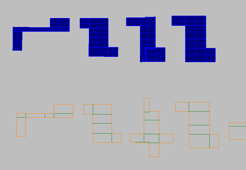
| Using a digital model to prepare cut files for a physical site model using the UNFOLDING method. Involves the Explode and Rotate3D commands, or the UnrollSrf command. | |
| Uses Tool(s) | |
For this workflow, we will be working on unfolding the buildings. The ground surface cannot be unfolded because it has doubly curved surfaces, so we will only focus on the buildings. However, we will make TWO SETS of cut files for the building--one set for a physical model made out of paper , and once for a physical model made out of 1/16" chipboard. Both physical models will be at 1/8" = 1'-0" scale .
Preparation
Before starting to prepare cut files, there are several steps to take.
Scale the Model
Use Save As to save the Rhino file as a separate file. This file will be used only for the preparation of files for physical modeling. Then, make sure no layers are locked and that no objects are hidden. Use the SelAll command to select all objects, and scale it to 1/8" = 1'-0".
Ground Surface
The ground surface has already been prepared for you using this workflow . The ground surface is now a closed polysurface (instead of a floating plane) and is ready to model. However, since we will not be tackling the ground surface in this workflow, turn this layer off .
Unfolding the Buildings - Paper Model
The quickest way to unfold buildings is to use the UnrollSrf command. However, this command is not perfect, and often times we have to manually perform the same action using the Explode and Rotate3D commands. Since these cut files are for a model made out of paper, we do not need to worry about material thickness, since paper itself has negligible thickness.
Automated: UnrollSrf
To use this command, select the first building and type UnrollSrf . In the command line, make sure that you do not select the Explode option, as this will separate all of the individual surfaces. Again, the purpose of the unfolding method is to minimize the number of cut+glued edges, and maximize the number of folded edges. In order for this to work, the surfaces need to remain as intact as possible after they are unrolled.Labels
If a particular building is made up of complicated surfaces, turn the Labels option in the command line on during the UnrollSrf command, so that there's a guide to what edges should be joined.Creating Linework
In the top view, the flattened surfaces will appear at the origin point. If it works successfully, there will be no overlapping edges. Now, it is time to extract the lifework from these surfaces. Use the Make2D command in top view to generate lifework. Make sure that the Tangent Edges option is turned on , otherwise the fold lines will not appear (only the perimeter cut lines will show up).Editing Linework
The next step is to clean up the lines (get rid of overlapping or duplicate lines). It's also very important to differentiate what lines will be cut all the way through the material, and what lines will only be cut partially through to create a folded edge. Create two new layers called "Cut" and "Fold." Add all of the perimeter lines to the "Cut" layer. Add all of the interior lines to the "Fold" layer.Think about where you want the glued seams of the buildings to be versus the folded seams. Don't forget that the linework can be manually edited after the UnrollSrf command is performed. Use the labels to move and rotate individual surfaces.
Manually Unrolling
In many cases where the object is complicated and/or has many individual surfaces that make it up, the UnrollSrf command will not work perfectly. The resulting linework may have multiple overlapping edges, which makes it impossible to cut out. In these cases, there are two options to proceed.
Unroll Portions
Split the original polysurface into smaller sections by using the Explode and Join commands. Then unroll these sections individually using the UnrollSrf command. Remember to label which edges will be joined, so you don't lose track of the pieces.
Explode and Rotate3D
It's also possible to do the entire unfolding process manually, which gives you the utmost control over how the surface is unfolded. Explode the polysurface. Select individual surfaces that you want to rotate, and use the Rotate3D command in the perspective viewport. The start and end of the rotation axis should be the endpoints of the folded seam, where the surface connects to an adjacent surface. The first reference point should be the current angle of the surface (click a third endpoint), and hold down shift to click the second reference point flat along the X axis (you may need to switch to the front or right viewport for this).Arranging Cut Files
Arrange the unfolded building surfaces in a row. Use the Text tool to label each object so keep track of the pieces. Keep the labels on a separate "text" layer so that they can be turned off later if needed.
Accounting for Material Thickness
Now that the first set of cut files for the paper model is complete, Copy the set over to the side. We will now edit this second set of cut files for a model that is made of 1/16" chipboard.
Editing Linework
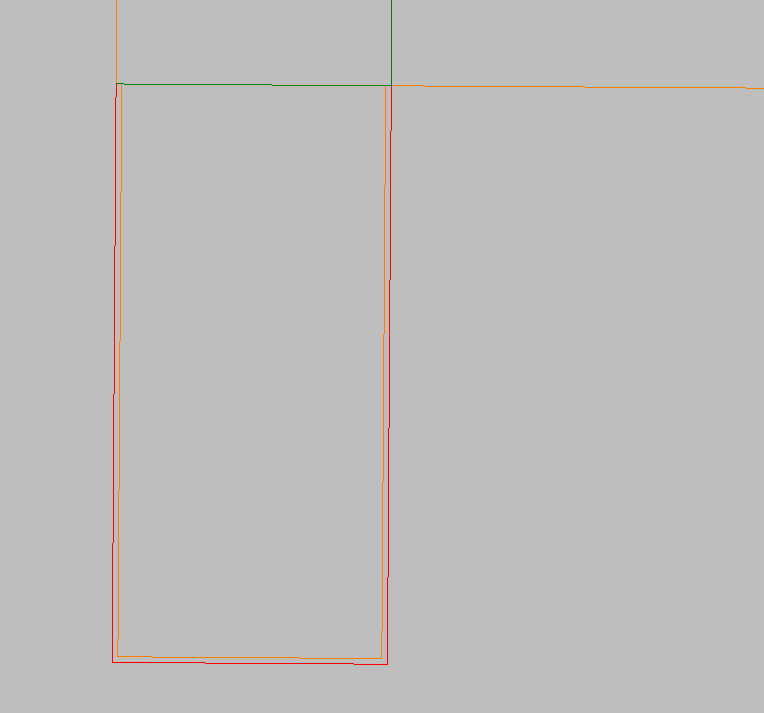
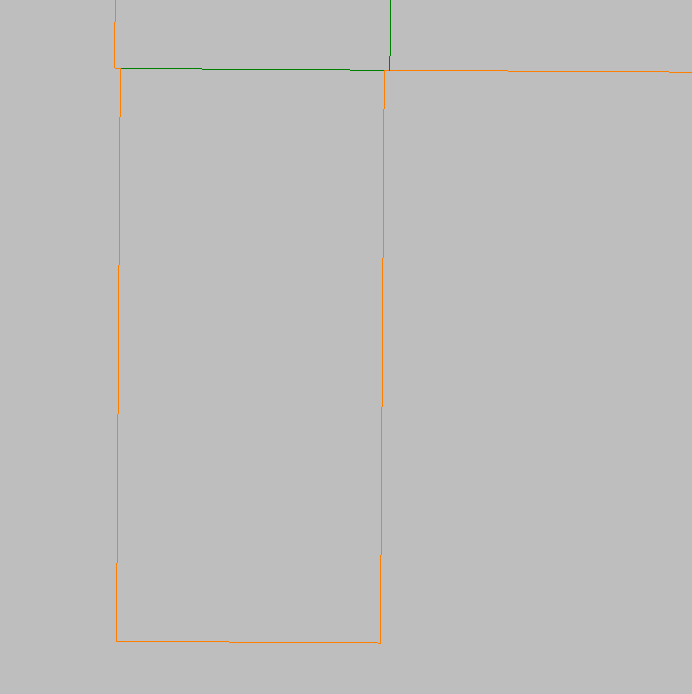
For every seam, you will have to trim one side of the seam to account for the material thickness (you can pick which side). This includes both folded and glued seams. Otherwise, the object will end up being larger than intended, and will not fit easily into the site model. It's important to be very precise about material thickness so that everything lines up and fits perfectly.Glued Corners
For glued corners, this will allow one piece to cleanly butt up against the other piece. It does mean that one edge of the material will show at each glued corner, but this is much easier than attempting to chamfer the corners (cutting both pieces at an angle so the outside edges line up perfectly).
Folded Corners
For folded corners, you will also see (most of) a material edge, but these seams are often preferable to glued seams because everything lines up cleanly (since the pieces are still attached). It also speeds up the time it takes to build the model.
Editing Tools
For this process, it will be helpful to use the Trim and Move commands to edit the linework at each seam. Be methodical about starting at one seam and working your way through the rest of the object's seams, so that you do not miss any.
Submission
Save the final result as a Rhino file (.3dm) and upload to your bSpace dropbox by the end of section.


