|
Making Orthographic Drawings with Site Context |
|
|---|---|
| Screenshot | |
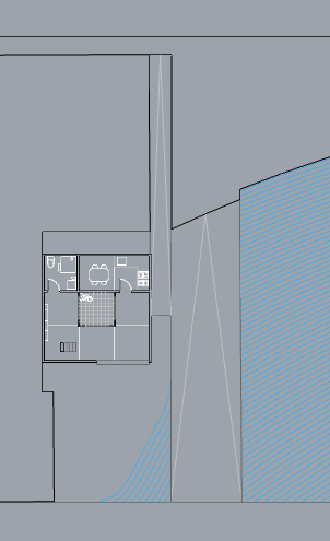
| This workflow demonstrates the process of creating a floor plan drawing with site context from a 3D Rhino model. The process includes cleaning up the output, deciding what information to keep / delete and what needs to be drawn to complete the understanding of the space. | |
| Uses Tool(s) | Rhinoceros for OSX |
Making Plan Drawing with Site Information
Please use the Rhino Model to follow the workflow.
Make a copy of your design model
When creating drawings, it is potential for some part of the model to be trimmed or deleted. Therefore, before starting the process, please save the Rhino file as a separate copy to avoid losing work of the original, complete digital model.
Create a Cutplane
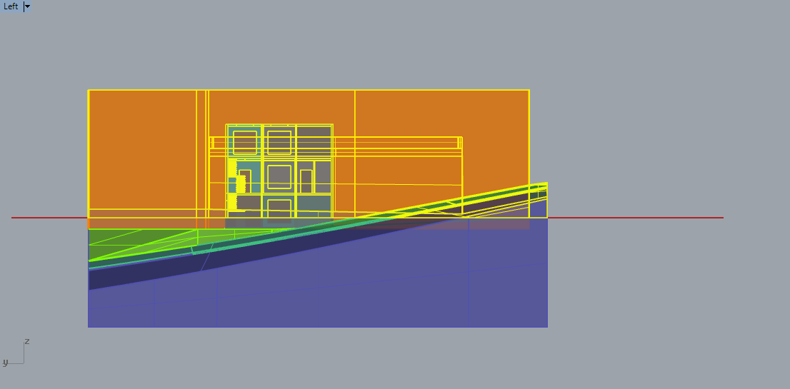
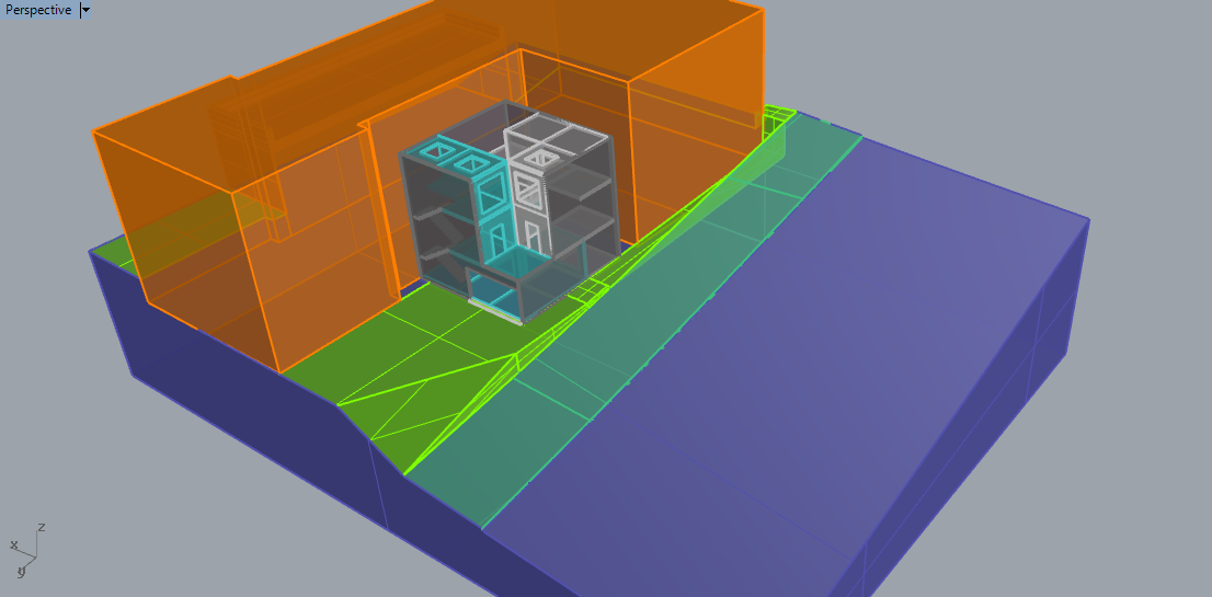
First, create a new layer called “Cutplane”. Make that layer the CURRENT layer by double clicking on it. Plans are always drawn with the section cut 3' above the floor, therefor this plane should be located 3' above the floor.
Move
it into place. Use the
CutPlane
to create the CutPlane. You can always select the plane and type
Move
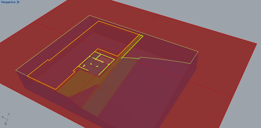
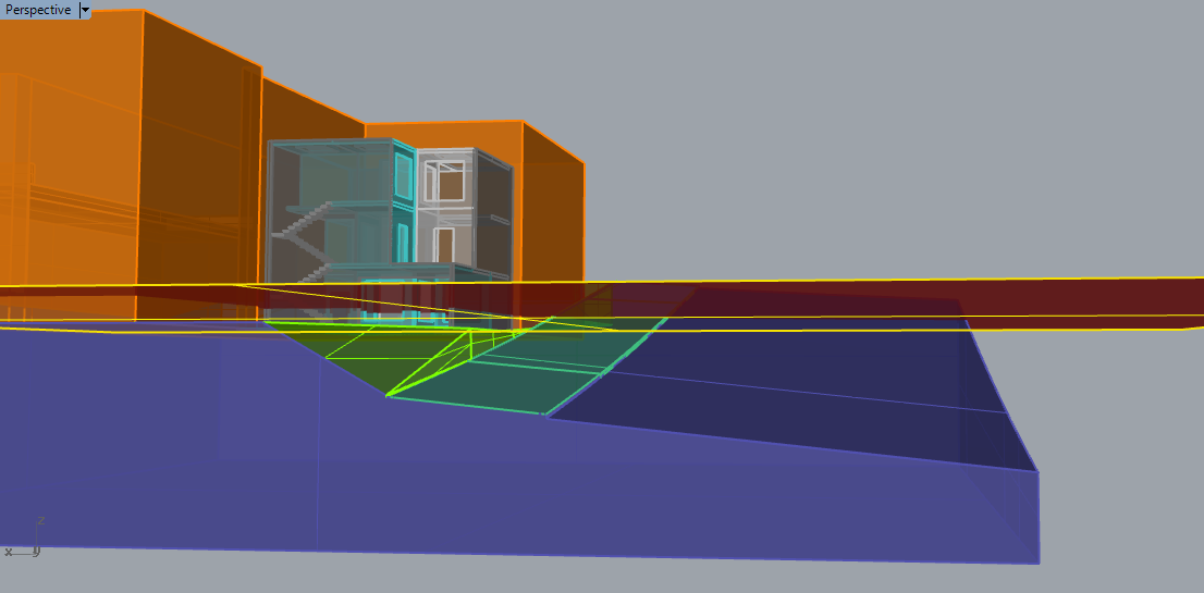
to move the plane to your preferred section cut. Your model should look something like this:
Split the Model with the Cutplane
The next step involves hiding half of the building geometry that is above the cutplane. First we need to split the entire model along this cutplane. Select the entire model and type the command Split . Select the CutPlane as the cutting object. This command may take some time because it is testing every surface within the model against the cutplane (which is why it may read in the command box "Split failed" for every surfae that is not actually crossing the plane). It might as well as turn the model back to wireframe to alleviate the process.
Cap the Cutting Edge
When looking at the plan view of the model ( the Top view), the model looks almost ready for flattening. However, when splitting the digitial model including the walls, floors and other closed polysurfaces, the sectioned model now looking into these empty spaces. To cap these"openings", we can use the Section command to generate the edge curves along the cutplane. After finishing the section command process, before deselecting these curves, we turn off the cutplane layer and use the PlanarSrf command to create the cap for the model.
When we are processing the PlanarSrf command, the option box might pup out, just click OK .
Make2D
Use the
Make2d
command to produce the 2D plan linework. Be sure that you are in the Top viewport. Start the
Make2d
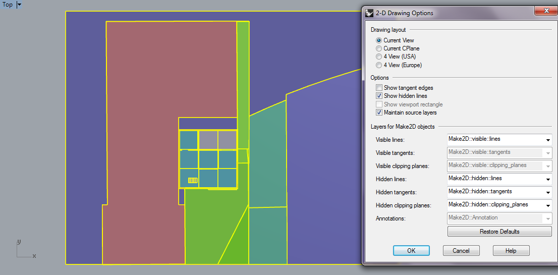
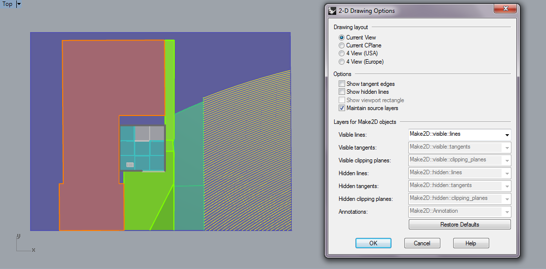
command, select the objects and press enter. For the 2d Drawing Options, choose Current View under Drawing layout. Check Maintain source layers, every layer will be maintained with a separate layer for Annotated, Hidden and Visible linework. Press Okay.
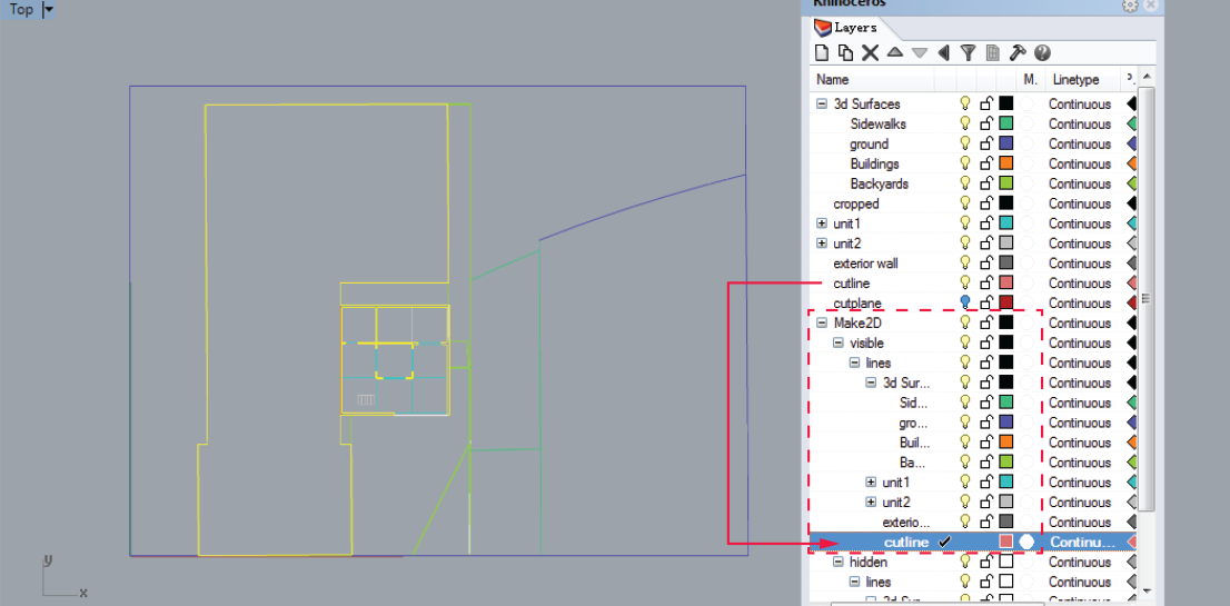
If you checked Maintain source layers, you will find out that the linework products applied the same color as in 3D version. That means all the layer organizations are reserved as sublayers in the Make2D layer.
Create Contours
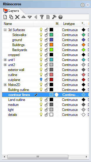
In this workflow, we want to include the site contours in the plan drawing. Create a new layer named as "contour lines" and make it to be the current layer before we start the process.
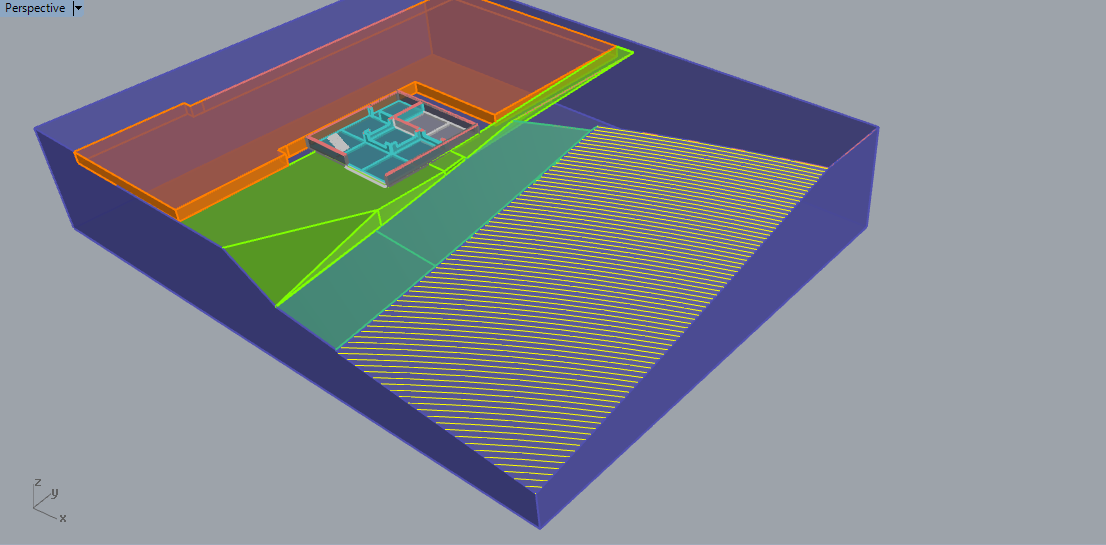
First step is to use contour command to create 3D contours from the topographic surface. Select the topographic surface and type contour , press enter and click two base points along an vertical edge, this specifies that the contours will be perpendicular to the vertical plane, which means that they will go horizontal. Type 1/4' for the Distance Between Contours option. (you can test different distances to see what line density is better to represent the topo surface.)
After creating contours, switch to Top viewport,
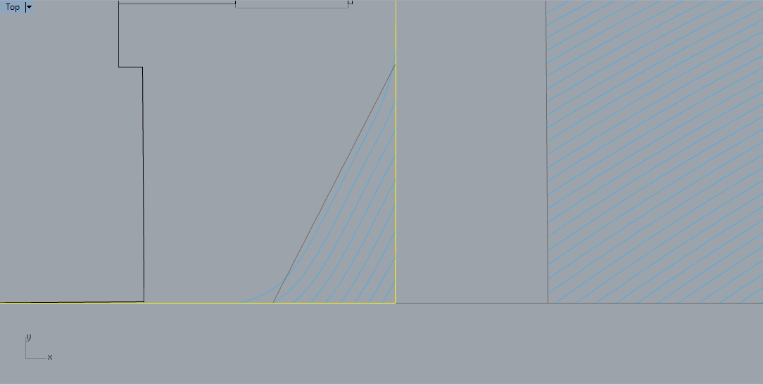
Make2D
those lineworks, and combine them with the 2D plan lineworks we generated in the previous step.
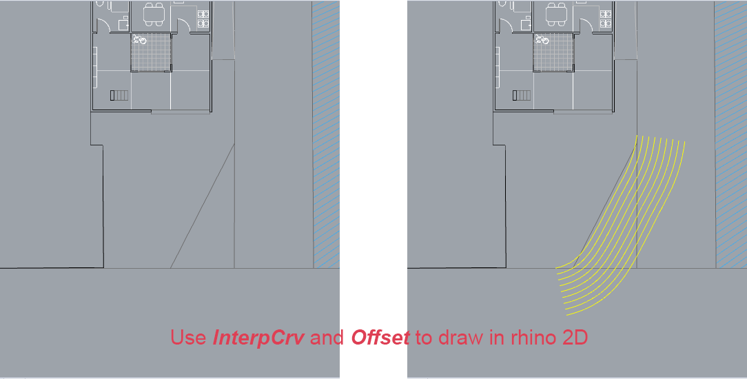
For some part of the landscape, we might use abstract geometries to represent the land. If we want to describe it more accurate, we can use the
InterpCrv
command to hand draw the contours and use the
Offset
command to duplicate the curve in specific distance.
 Trim off unwanted curves.
Adding details
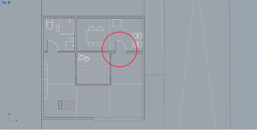
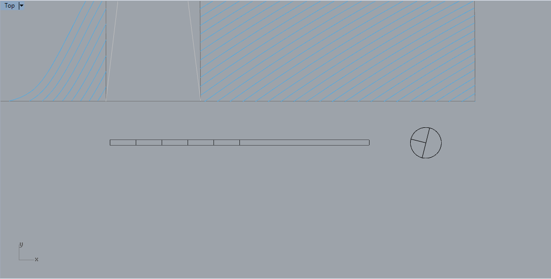
We will add architecture conventions in the drawings such as door swing, ramps, mullion, graphic scale, north mark. It would be easier to assign lineweight if we draw them in the same layer.

