|
Creating a 3d Kayak |
|
|---|---|
| Screenshot |

|
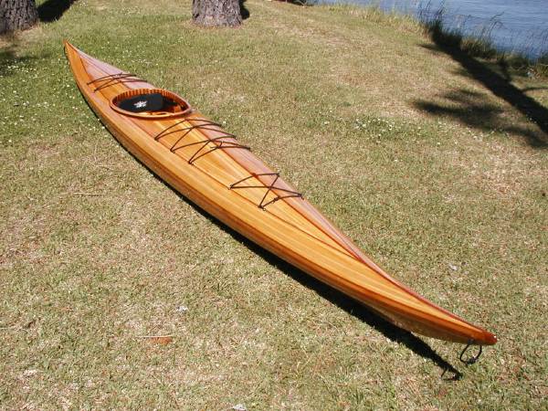
| Using a set of standard 2D hull construction drawings, students will construct a 3d model of a Guillemot S-Series Kayak. This task will require the use of 3-dimensional translation, precise geometric positioning and orientation, and the use of construction geometry to produce high-level forms. Students will be provided with a vector-format representation of the hull contours (already traced), and will be expected to produce a complete surface model (as a minimum) in the time allotted. | |
| Assessment objectives |
Fluency in basic surfacing modeling will be reflected in students' ability to:
|
| Exercise Type | Problem Set |
| Evaluation Criteria |
|
| Uses Tool(s) | Tool:Rhino v4.x |
| Uses Workflow(s) | Workflow:555376 |
Using the 3d file provided below, digitally recreate (using Rhino3d) the Kayak with NURBS surfaces. Be as precise as possible, using the short contours to properly model the hull. The hull itself should be "watertight" - meaning there are no holes and all edges on the exterior surfaces are touching. Additional elements, such as a trimmed opening and exterior piping can be added afterwards.
There is an existing workflow that goes over how to do this that will help. It is for a more advanced version of the same assignment, so many of the 2d steps will have already been done. Please reference it for help with setting up a jig and working in 3d.
Jigs and Construction Geometry
No printed drawings are required for this exercise, please submit a digital model via email to the address below:
SUBMISSION EMAIL: upload.SUBMITT.zvy2450uje@u.box.com
Instructions
- 1. Download the Kayak File
- Download the file from the link provided below.
- 2. Draw Section Lines
- First, trace the short section lines of the kayak from the included scanned drawings. Construct these lines from NURBS curves with as few control points as possible to approximate the given geometry. Place these lines onto the layer "Short Section Lines". Note the position of these lines have been labeled for you - seven 'stern' lines and eight 'bow' lines - with labels in each of the areas that you'll be working.
- 3. Scale Section Lines
- Position your traced section lines in the first gridded box to the right of the scanned drawing, and then scale them to match the second (smaller) gridded box that has been scaled to match the drawn plan and elevation.
- 4. Position Section Lines in 3d
- Using the orient 3pt command, position each section line in three dimensions using the "3d jig" provided.
- 5. Create Kayak Surfaces
- Using the section lines as a guide, create lofted surfaces that approximate the kayak. You may not be able to do so using just one operation, and will have to rely on several sweeps and/or lofts to complete the surface. Note that the end caps of the kayak are not accounted for by the process described above, nor is the opening for the rider of the kayak. You will have to improvise to complete a water-tight kayak surface (hint: the hole for the rider could be filled in, as if covered with some material, such that the thickness of the wall of the kayak need not be represented.
- 6. Detail Kayak in 3d
- As time allows, you may now detail the kayak in 3d based upon the surfaces you've constructed thus far. Possible details include a lip around the hole for the rider, modeling two surfaces that show the thickness of the wall of the kayak, and plank lines that show the boards that makeup the surface of the kayak.
Files
A file with the construction lines and the plan and elevation already traced has been provided for you to save time, and is available at the link below. Note the layer structure.
Resources
- Architectura Navalis by Fredrik Henrik af Chapman
- A volume of drawings which exemplified the best and most interesting naval vessels of the time. The work was published in 1768.
