| Creating a Layout for Plotting | |
|---|---|
| This method will Illustrator how to create layouts in Autocad which involves working between the paper space and model space. Starting from finished linework, this method will teach how to place artwork at scale onto a page and print to PDF with attributed plot styles. | |
| Part of | AutoCAD 2012 |
| Part Type | Method |
| Screenshot |
|
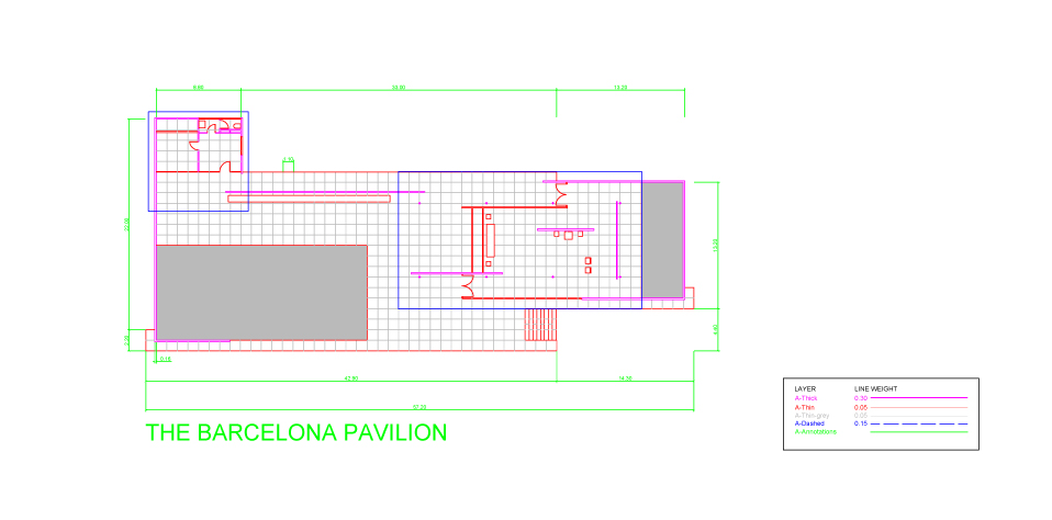
This workflow goes though the steps to creating layouts using the paper-space feature in Autocad.
Steps
Setup Page
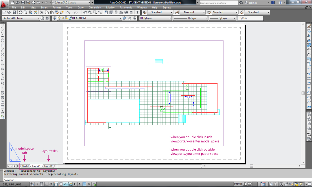
When opening your work in AutoCAD, you will likely be brought immediately into the model space. In the lower, left-hand corner, there are a series of tabs - in which the "Model" tab is currently selected. Some of these should be blank layout tabs. Select one of these tabs and you will then be viewing one of layouts. You can always make a new layout tab by right clicking on one of the tab and selecting "New Layout".
In the layout tab, you will automatically be in paper-space. Anytime you double click in one of the viewports, you are transported to model-space . You can also type MSpace or PSpace to move back and forth between the two - which will be discussed further in the next step.
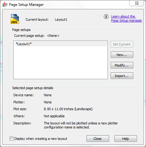
Before setting up the different viewports, it is important to setup the page itself. Go to File -> Page Setup Manager. In this first menu, you can see a few details on the different layouts, create new layouts and edit existing ones.
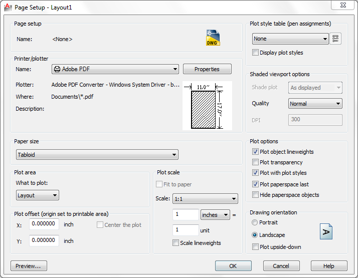
In the layout options, be sure to select the Printer you are going to use. Select "PDF" so that in the final step, we can remove the Educational stamp by opening the file in Illustrator. Also select Paper Size, Orientation and Scale (which should be 1:1).
Add Viewports
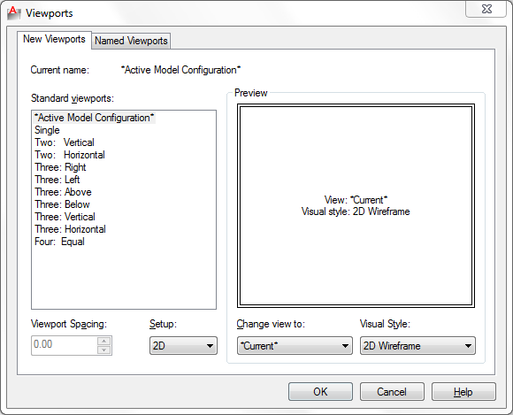
When opening one of the layout tabs, there is usually already one viewport placed in the center of the page. To make a new viewport, type the command
Viewport
and a new menu will appear for different options. Select SINGLE to create one viewport by clicking on two opposite corners of the frame. Note that the outlines of this viewport are lines from whatever layer you are working in and unless they are located in a non-plotting layer, will show up when you print. You can change these settings later on in Step 4.
Another way to easily create viewports is to use the Viewport toolbar. To access new toolbars, right click in the gray area of the top toolbar (where no icons are located). A list of available toolbars should appear. Click on the "Viewport" option and a toolbar like the one above will appear. Now you can easily select different Viewport options to add to the page.
Create a Viewport for the plan drawing that fills the page.
Edit Scale
The viewports provide views into the model space of the drawing - exhibiting the linework that is created in the "model" tab. The advent of paper-space is being able to layout the viewports at different scales and add notations without affecting the original linework.
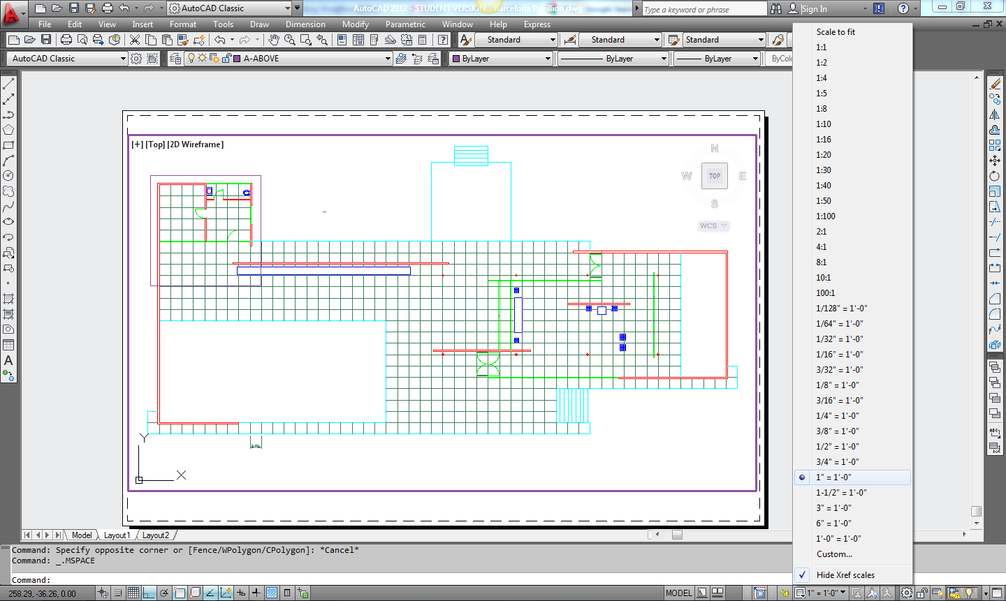
When double clicking on a viewport, as previously mentioned, you are able to enter model-space and move around the location of the viewport. You must be in the model-space of the drawing to move around and pan what the viewport is "viewing" and to change the scale of the drawing. Notice how the bottom toolbar automatically changes when you go from paper-space to model-space. In the model-space, there is a scale button which allows you to automatically scale to a certain size.
After scaling the drawing, select the lock icon next to the scale toolbar. This will lock the drawing at the scale you have selected so that you do not accidentally alter the view.
Add Labels
Underneath every viewport, use the Text tool to label the type of drawing and the scale. You can also add leaders (arrows) to further label the drawing.
These notations should be in a layer solely for adding notes in Paper-space.
Edit Plot Styles
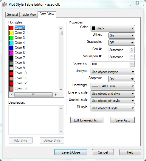
Before plotting, you can edit the Plot Styles of the drawing so that the different layer colors are automatically converted into linework with a specific weight, color and dash. When working in an office, typically there will be a large Plot Styles setup which all drawings are coordinated with, with sometimes hundreds of layers organized by color and detail. For this workflow, we will just edit the layer colors that we know exist in the drawing.
Go back to "Page Setup Manager" and select the layout you are working on. In the top right corner is the Plot Styles list. Select "acad.ctd" and click on the "Edit..." tool right next to the drop down menu. Here, you can select a color on the left which refers to every layer that is in that color, and the Pen Assignement on the right, which is how it will be plotted in the drawing. Be sure to change the Color and the Lineweight.
Change all the layers in the drawings to the correct lineweights and color and then press Save + Close. You can now preview what the layout looks like by selecting the Print Preview option in the toolbar.
Plot
At this point, you can print your drawing to PDF. Press on the print icon in the top toolbar and the printing menu should pop up. All of these settings should already be setup accordingly because we have edited the Page Setup options. Simply select "Print" and save the file in an easy-to-find location.
Refine Drawing in Illustrator
The drawing is now "plotted" and ready to send - however, being that we are using the Autocad Education program, there are stamps around the border of the drawing that state "PRODUCED BY AN AUTODESK EDUCATIONAL PRODUCT." To remove this, as well as edit any linework further, you can open the PDF in Illustrator.
Notice that all of the linework is automatically located on the same layer. If you wish to work more in Illustrator, you can use the Select tools to re-organize the layers according to lineweight. Otherwise, simply select the border text and delete it. You can resave the finished file as a PDF.
