| Placing an Isometric Camera View | |
|---|---|
| This method looks at how to place the camera and target in a digital model to achieve a true isometric view. | |
| Part of | Rhinoceros |
| Part Type | Method |
| Screenshot |

|
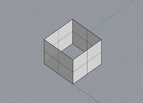
Isometric drawings use equal angles of 120º and is the most commonly used form of axonometric projection because of its ease of use with a 30º-60º triangle and clear representation. There is equal foreshortening on all sides (80% of the true size) and thus the plans and elevations cannot be used as base drawings.
Steps
Defining the Camera Location
In top view, draw a perpendicular line from the corner of the object that will be the focus of your isometric view. Next, remaining in top view, rotate the line 45 degrees from the orthogonal direction.
Now we will want to rotate the line we just drew 45 degrees up so that our camera will be at the appropriate height and angle for the isometric view. Using the 3-Point CPlane command, set one end of the line as the CPlane origin, the second end of the line as the x-axis direction, and the vertical corresponding edge of the object as the y-axis direction.
Now, in perspective view, rotate the line up 45 degrees on our newly defined CPlane .
Once you have done this, move the line vertically up to the top most corner of the object for which we are creating the isometric view.
Placing the Camera and Target
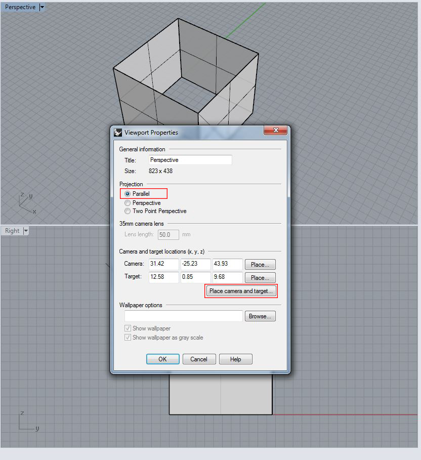
In perspective view, open the Viewport Properties . Since isometric drawings are parallel to the plane of projection, select parallel as the projection type. Next, under the camera and target options of that same dialogue box, select the Place Camera and Target button.
Still in perspective view, select the higher point of the line we just drew as the camera location, and the lower corner of the line (which should correspond to the uppermost corner of the object) as the camera target. Hit OK .
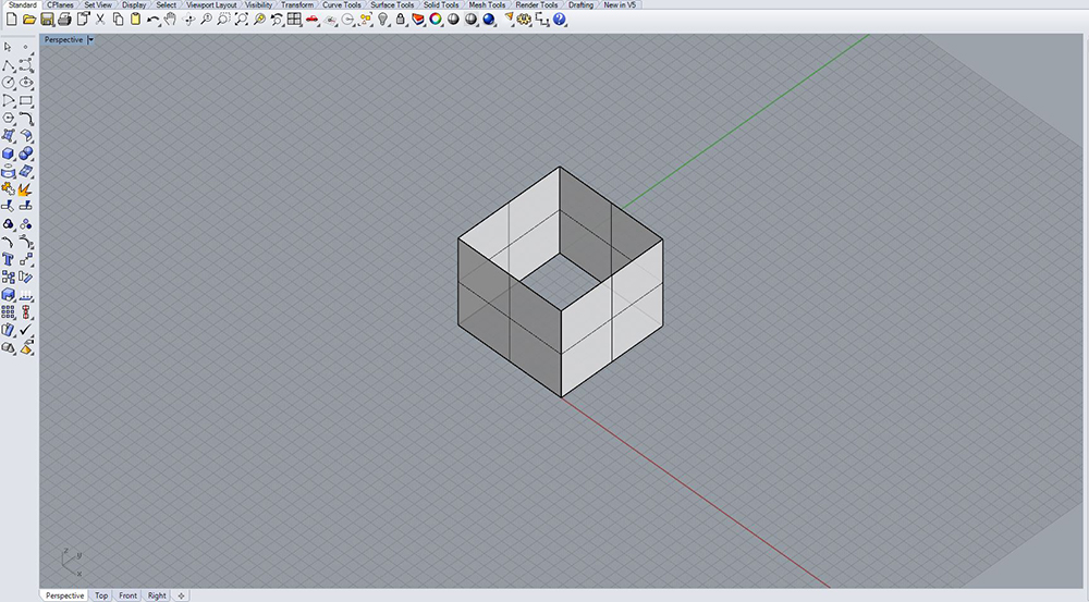
In perspective view, you should now see the object in true isometric view. Zoom in or out as necessary and be sure to save your new view for future reference.


