|
Drawing a Complex Surface Using the Topography Contour Method |
|
|---|---|
| Screenshot | |
| When graphically depicting a complex surface, most notably a complicated site topography, it is often useful to draw the set of curves that result from the intersection of the surface with a set of imaginary planes. This method is commonly used in the production of topographic maps, but may also be used in other contexts. | |
| Uses Tool(s) | Rhinoceros , Illustrator CS5 |
Steps
Model Preparation
Before we start, let's ensure that we have all the necessary geometry to complete the process, and that it is organized in a useful way. Ideally, we should have all the items listed below:
- Clean Surface Geometry
- Ideally, we should have just one single polysurface that represents the ground.
- Well-Organized Layers
- Any building massing or other objects that will not be depicted on separate layers that may be switched off.
- Saved C-Planes
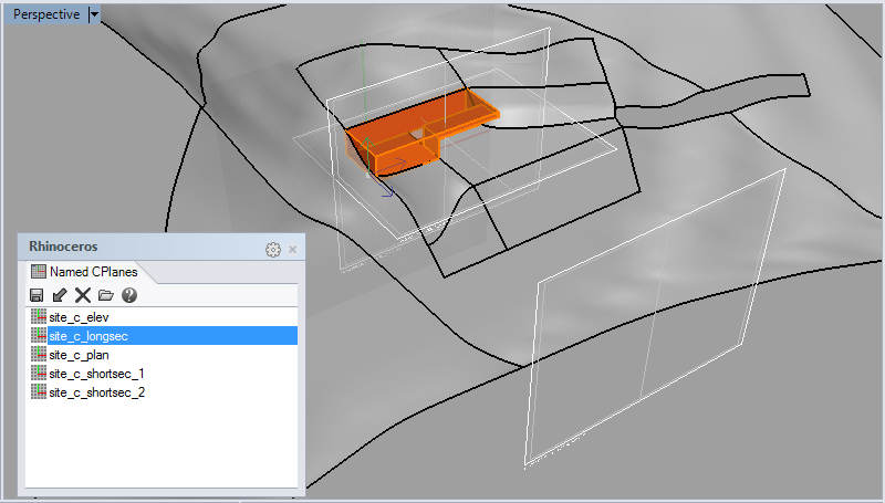
- We should have saved c-planes in strategic locations, including the intended projection plane of our drawing
- Drawing Frame
- The boundaries of our intended drawing should be modeled on the c-plane described above, including the size and orientation of the paper.
Splitting the Ground
Start by making a copy of the surface that represents the ground, moving this copy to a new layer, and turning off the layer that contains the original ground. This will ensure that we don't lose any information in the process below.
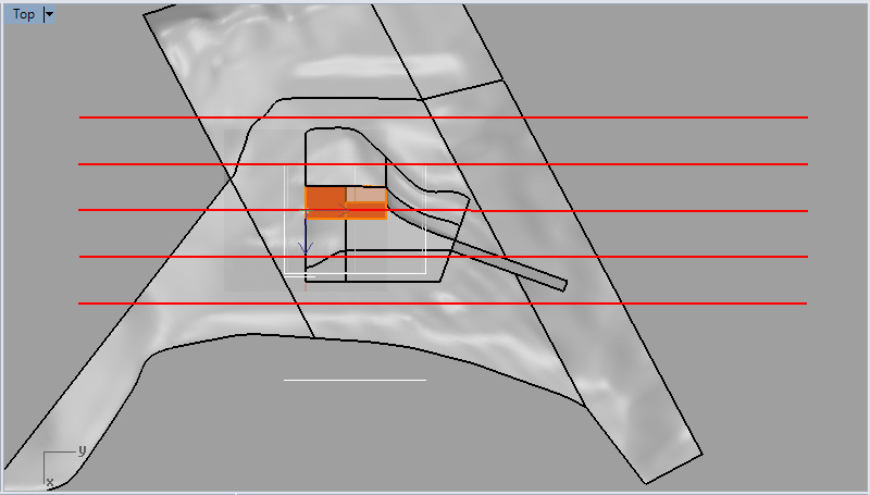
Next, place a set of slice planes that intersect with the ground, parallel with the draw plane. We'll use these to split the ground into convenient fore, middle, and background lines for the drawing that will be drawn with different lineweights, so think about what divisions will be useful to your drawing. Ensure that these planes are spaced at some reasonable increment - for example, snapping to the nearest foot or five-foot increment. Failing to do this may result in odd gaps between the contours of each slice.
Now, using the planes we have constructed, split the ground using the Split command.
We may now delete our slice planes.
Note that the newly sliced ground may have been split into multiple disconnected pieces. If this is the case, you may want to join or group these pieces together for easy selection later.
Contouring
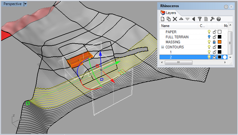
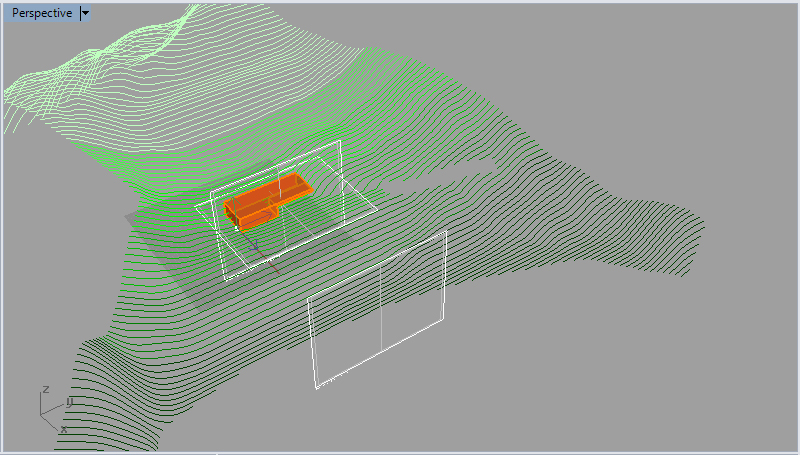
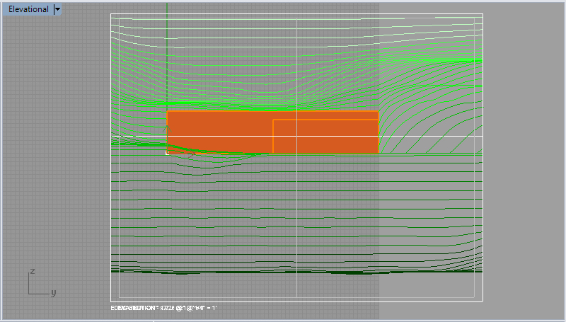
Next we will produce contours for each slice of the ground, one by one. Use the contour command for each slice of ground individually such that every group of contours produced may be moved onto a separate layer created for this purpose. Using sublayers will keep your model tidy - the image below shows the second of contours being moved onto a layer called "2", which is a sublayer of the "CONTOURS" layer.
Remember that our sliced ground may have been split into multiple disconnected pieces, so we should be sure to select all the relevant pieces when contouring each slice.
After contouring, we may delete our split surfaces, leaving just the contour lines visible, as seen below.
Contour Cleanup
Any lines that would not appear in the drawing should now be removed. This would include any lines that would be obscured by another part of the surface, and lines that may be obscured by an architectural intervention or other geometry that has not been contoured.
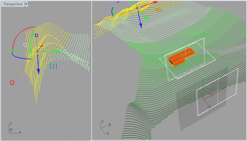
Below we can see that the contours highlighted in yellow would not be visable from the position of our drawing, because they lie on the hidden side of a ridge. Lines such as this should be deleted before moving on to the next step.
Projection of Contours to C-Plane
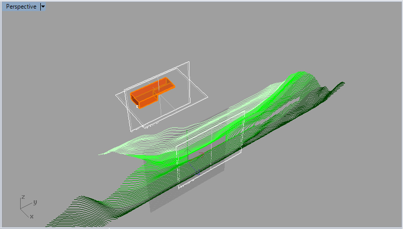
Next we will 'flatten', or project the contours we have created onto the plane of our drawing. First ensure that the c-plane is set such that it lies in the plane of our drawing. Then, using the ProjectToCPlane command, project the contour lines to the c-plane, deleting the source objects.
Trimming Contours to Drawing Frame
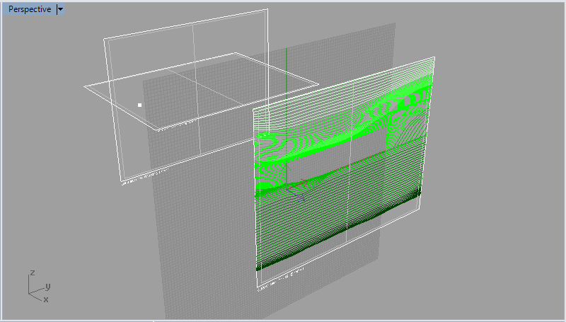
Now that our contours are "2d", in that they all lie in the same plane as our drawing, we may trim these lines to the frame of our drawing and delete any lines that would not appear.
Exporting and Polishing
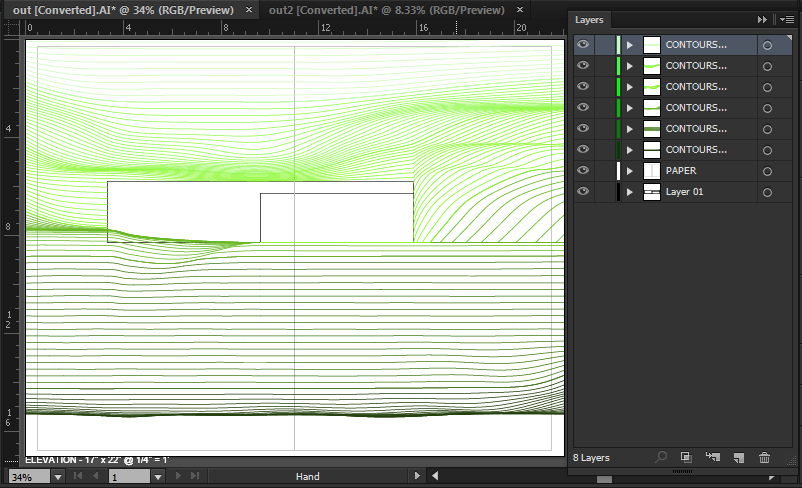
Our contour lines are now ready to be exported to whatever context in which we will be preparing the finalized geometry. Remember, when exporting to programs like Illustrator the drawing must be scaled and it must be over or very close to the X, Y intersection in top view. If not it will not appear on Illustrator's drawing board.
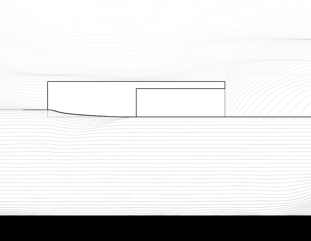
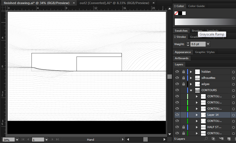
In the final drawing shown below, that the layers of contour lines have been assigned a gradient of line weight, line style, and line color in order to archive the subtle depth effect shown. although six layers of contours were originally produced, a number of "half step" layers were required to smooth out the transitions from layer to layer.
