|
Extracting Line Work from a 3D Massing Model |
|
|---|---|
| Screenshot | |
| This workflow describes the steps necessary to create a drawing set of a simple massing form. Students will learn how to cut an existing model, use viewports to create plan and section drawings, Make2d, organize layers for efficient editing in Illustrator, and exporting drawings to scale. Digital lineweights and standards are described along with the basic drawing tools in Illustrator. | |
| Uses Tool(s) | Rhinoceros , Illustrator CS5 |
For this workflow we will be using the following file: Double Negative
Steps
Copying the Original Digital Model
In order to continually refer to our 3d model, it is important to copy it before cutting plans and sections from it. We will be cutting this particular model four times, and therefore should make four copies of the model.
Also, it is important to consider the location where the model is being copied to. We will be taking short and long sections of the model, and therefore be using the respective FRONT & RIGHT viewports when making our drawings. In order to avoid any overlap between multiple model copies, it is useful to organize them diagonally from one another.
We can draw a construction line extending 45° from a chosen edge our the model. To do so, first, create a new layer, name it "construction" and double click it. Now, working within our new "construction" layer, type Line . Note, within the top command line, we have several options to choose from. In order to ensure a precise 45° angle, either type A or click "Angled."
Following the directions within the command line, use a corner of the building for the "start of base line" and use an adjacent edge of the model for the "end of base line." Now type 45 for the "pivot angle." Draw the line long enough to attach four copies of the model.
- Construction Line
Type Copy , select the corner of the model that the line was drawn from (using your OSNAPS) and copy it four time along the construction line so they do not overlap within the FRONT & RIGHT viewports.
- Model Copied Diagonally & Without Overlap
Sectioning the Model
Now that we have our models organized, we can Delete or Hide our construction line.
Type CutPlane and select the first model for sectioning. We will be taking a short section and will determine the placement of our cut plane accordingly. For this particular model, it is important to describe as much void space as possible. Using the FRONT viewport we can clearly see where a cut plane could be placed in order to cut through the interior void spaces. Within the FRONT viewport, start the cut plane underneath the donut shaped void space.
Now, using the PERSPECTIVE viewport, and while holding the SHIFT KEY to enable ORTHO mode, draw the end of the cut plane extending beyond the edge of the selected model.
A cut plane will appear.
- CutPlane
Now, we will use the cut plane to create our section cut. Type, Section . Select the model to be sectioned. And for the "start of section" select a corner of the cut plane. For the "end of section" select the opposite corner of the cut plane.
Notice, new line work appears and is automatically selected. While selected, use the Properties panel to assign the section line work to a new layer. Title this layer "section."
- Section Line Work and Layer
Now that we have our section defined, we need to actually section the model into parts. Type Split . Select the model. And for the "cutting object" select the cut plane. The model will be divided accordingly.
Select the portion of the model that has been cut away, and Hide it.
- Model Split and Hidden
Correcting the Split Model
If we Delete the cut plane, we will notice that the digital model appears hollow where it should read as solid. This is because Rhino uses surfaces to compose volumes. We erroneously interpret closed volumes as mass.
- Hollow Model
We can solve this problem by Cap ing the sectioned model.using the cut plane as a surface to conform to the edges of our section cut.
First, within the Layers Panel, right click on the "section" layer and from the drop down menu select "Select Objects."
Now, with the section lines selected, type Join . You will notice within the top command line that "two closed curves" were created. Curves in Rhino refer to lines. When they are closed it means that they create a loop. It is important to have closed curves for all section lines.
In order to close the hollow end of our split model we are going to Trim the cut plane from the section closed curves.
Now, Join the trimmed cut plane and the split model. Note: After joining, the model may automatically become assigned to the layer that the cut plane was a part of. To correct, simply use the Properties panel to revert.
Note: We could have also used the Cap here. However, it is important to remember to Join the section lines.
- Model Joined
Make 2d
Now you can perform a standard Make2d operation on the visible layer. The resulting 2D geometry will go to the origin (0,0,0). Notice the layers on which this new geometry has been placed.
When complete, move the new line work away from the origin and clean up the hidden lines. Often times, there are too many and they can confuse one's spatial understanding of the form. Compare to the digital model and edit accordingly.
- Make 2d with Edited Hidden Lines
Organizing the Line Work
After creating three more sections and an elevation of the digital model it is important to organize them into a layout that describes their relationships accurately.
Starting with either a plan, section, or elevation begin to draw construction lines that extend from its respective corners.
Align the remaining line work so each cut relates back to the others.
- Construction Lines
Create a new layer and title it "annotations". Within this layer create Line s that indicate where the cuts were made throughout the model. You can accurately annotate the placement of these section lines by Copy ing the models and positioning them in alignment with the 2d line work.
- Creating Section Annotation Lines
Finally, clean up the construction lines and annotation lines using the Trim command.
- Trimmed Construction and Annotation Lines
Organizing Line Weights & Types
Now that we have all of our line work organized into a single layout, it will be useful to take the time to organize the line work into discreet line types.
To begin, it is useful to Purge all unnecessary layers from the document. After doing so, you will notice that many extraneous layers will have disappeared from your Layers Panel.
Now, working sequentially, use the appropriate model to identify which lines within the respective Make2d drawing are in the foreground, middle-ground, and background. It is helpful to Move the needed model near the appropriate drawing and work within the PERSPECTIVE viewport.
- Identifying Line Weights
Create three news layers and title them by general line weight type. For example: Thick, Medium & Thin. Select the appropriate lines (based on your observations of the digital model) and assign them accordingly. Thick lines will be the closest to the foreground and thin lines will be the furthest away.
- New Layers
Creating Fill Layers
As before, we will use the digital model to understand how we will shade the surfaces that rest in elevation and behind the section plane. Create three new layers for different tones. Example: light fill, medium fill & dark fill.
- New Fill Layers
Starting with the "light fill" layer, use the Polyline tool to trace over the edges that define surfaces that are in the foreground. When creating fill layers it is important to treat them like a section cut. Make sure to create a "closed curve" by ending the polyline at the exact point in which it was started. Note: The "light fill" surfaces will reflect the "light" line weight layer that was previously defined.
Continue this operation for subsequent fill layers. Some areas to fill are already defined as "closed curves." Within our specific model they are represented by many of the curvilinear holes. For these simply Copy them Inplace and assign them to their rightful "fill layer."
- Trace & Copy Fill Layers
You will notice that there are some areas that cannot be easily traced or copied. This is because they contain curvilinear curves and are represented by two or more objects. For these situations we will use the Trim command. First, Copy the objects that define the area to fill away from the drawing.
Trim the objects accordingly and Join the remaining curves into a "closed curve." Finally, using the Properties Panel, assign the new closed curve to its rightful fill layer and Move it back into its proper place within the original drawing.
- Trim & Join
Exporting Line Work
Select all line work to be exported and Move it to the origin of model space. You can do this by typing 0,0,0 after selecting the "point to move from."
Next, type Export . A dialog box will pop up. Make sure to save the export as a .ai (Adobe Illustrator) file. This format can easily be selected from the drop down menu.
Afterward, a new dialog box will appear asking you to define the scale of the exported line work. For this particular example, choose 4" = 1", or quarter scale.
Setting up the Illustrator Document
Open the exported .ai file in Illustrator. You will notice that the exported line work is positioned awkwardly on the page. To correct this we will use RULERS in order to adjust the dimensions of the ARTBOARD.
First, open rulers by selecting "View > Rulers > Show Rulers" from the top drop down menu. You will notice the a ruler tab opens along the top and left hand margins of your document. Note: the shortcut for opening RULERS is Control + r key.
Now, to adjust the artboard dimensions select the Artboard Tool from the left main toolbar. The shortcut is Shift + o . You will notice a bounding box appear along the edge of the artboard.
Before adjusting, we need to align the ruler with the edges of our artboard. To do so, move your cursor to the top left corner of the rulers and click and drag crosshairs to the top left edge of the artboard. You will notice that the ruler measurements now begin from the top left corner of the artboard.
- Rulers & Artboard
We can now see that our line work will comfortably sit within the margins of a standard 8.5" x 11" document. Using the bounding box, adjust the artboard accordingly. To move our line work back onto the artboard, Control + a , or SELECT ALL, and drag to the artboard.
We can center the our line work on the artboard by referring to our RULERS. Simple drag GUIDES from them onto the artboard. Since our document is 8.5" x 11", we will drag a GUIDE to 4.25" along the x-axis, and to 5.5" along the y-axis.
With the line work selected, use the bounding box to center the drawing on the artboard.
- Guides & Centering
Layers Panel & Color Panel
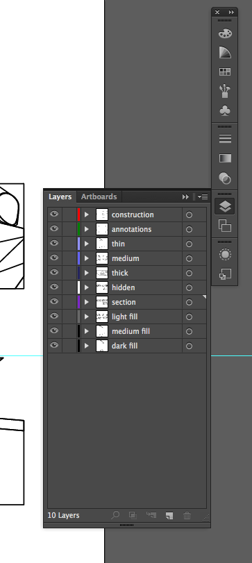
From the right tool bar, open the LAYERS PANEL. You can also open it by selecting, "Windows > Layers" from the top drop down menu.
Notice that the layers that we created in Rhino are preserved within our Illustrator document right down to the color that Rhino assigned to each layer.
- Rhino Layers Perserved
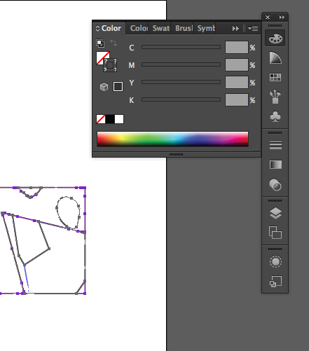
For our drawing we are going to want all of our line work to be black. We can quickly achieve this by, Control + a (select all) and opening the COLOR PANEL from the right tool bar. You can also open it by selecting, "Windows > Color" from the top drop down menu.
- Color Panel
Notice, the hollow box icon has question marks throughout it. This is the STROKE icon. Because we have all of our line work selected, and all of our line work is different in color, it cannot determine a single color to present. We can quickly chance all of our line work to black by selecting the BLACK BOX beneath the STROKE icon.
Organizing Layers
One fundamental difference between Rhino and Illustrator is how layers interact with one another. In Rhino, the sequence in which layers are organized does not influence our viewing of the content within them. On the other hand, in Illustrator (and Photoshop), the sequencing of layers determines what is visible and what is not. It is important to remember that if a layer is above another within the LAYERS PANEL, then its content is literally resting on top of the layer on the artboard.
We are going to be filling in our section cuts and elevations with color. If these layers are on top of our line work layers then they will obscure our ability to view the line work.
Reorganize the layer sequence within the LAYERS PANEL so the section and fill layers are beneath all of the line work layers. You can do this by manually dragging individual layers accordingly.
- Layers Organized
Filling the Section Cuts
Now that we have our layers organized, we can begin to use FILLS in order to describe the section cuts and the surfaces in elevation.
First, select all of the line work within the "section" layer. This is easily done by clicking on the circular icon to the right of the layer within the layers panel.
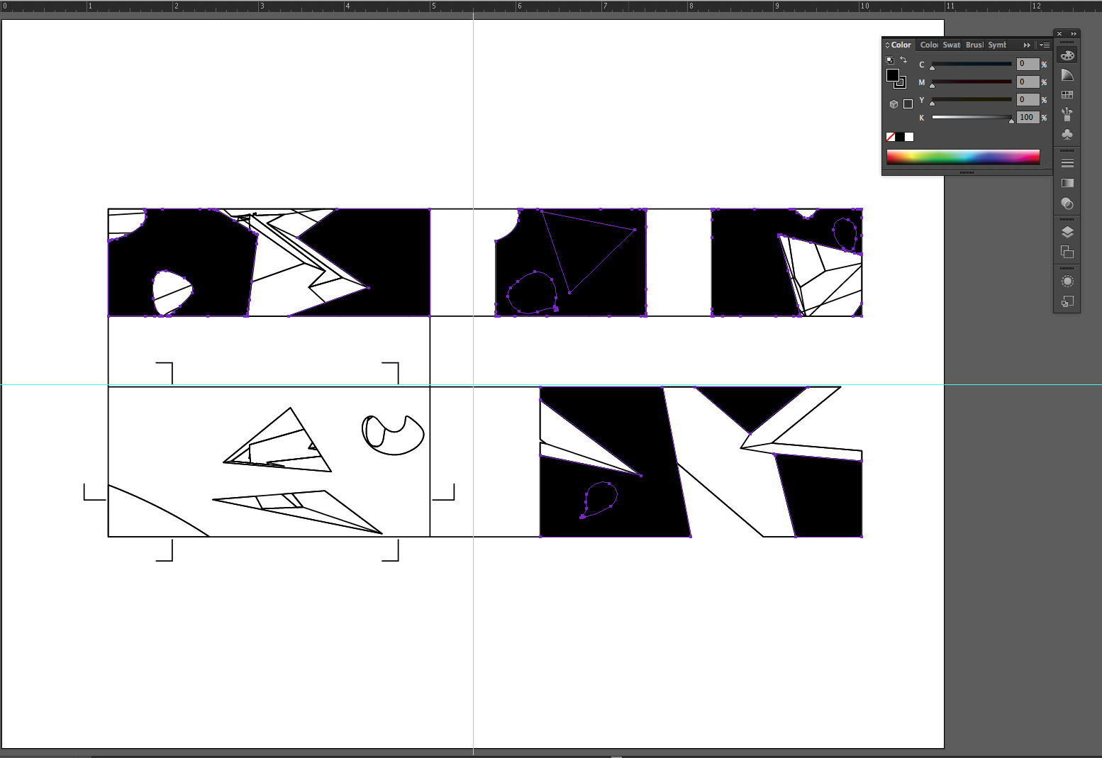
After selecting, make the FILL black. FILL is the complete square icon that is next to the STROKE hollow square icon within the COLOR PANEL.
- Section Filled
Notice how the section cuts that we assigned in Rhino have been filled with black. We can see that the smaller openings throughout each section have erroneously been included within the fill. Undo, or Control + z the fill command.
Now, to carry the operation out successfully, select all contents of the "section layer." And open the PATHFINDER PANEL by selecting "Window > Pathfinder" from the top drop down menu.
Click on the DIVIDE button within the PATHFINDER PANEL. It is the one near the bottom left corner.
- Divide
Now the smaller section holes have been divided away from the larger section cuts. The last step before we can remove the smaller holes is to UNGROUP them. With the "section" layer selected, either select "Object > Ungroup" or simply press Control + Shift + g .
Again, FILL the section layer contents with black. Now we can simply select the holes that we ungrouped and delete them.
Finally, select the "section" layer contents and adjust the tonal value of the black fill within the color panel. You can do this by manually adjusting the slider for the black, or grayscale, value.
- Tonal Adjustment
Adjust the section FILL to 85% black.
Filling the Elevation Surfaces
Now we will treat the elevation surfaces in the same manner as the section fill. Make the FILL values for the surfaces as follows. Also, while changing the FILL values, make sure to remove their STROKE value. This can be done by selecting the icon of a white box with a red line through it.
• Light Fill Layer - 5% black
• Medium Fill Layer - 20% black
• Dark Fill Layer - 60% black
Feel free to experiment with different tonal values.
- Filling Surfaces
Adjusting Line Weights
Now we can begin to adjust the line weights within our drawings. Open the STROKE panel by either selecting it from the right tool bar or selecting "Window > Stroke."
Within the drop down menu we can select different line weights. We can also manually type in our own line weight values within the same field.
- Stroke Panel
Select individual layers and assign them the following stroke values.
• "Section" Layer - 1pt
• "Thick" Layer - .75pt
• "Medium" Layer & "Annotation" Layer - .5pt
• "Thin" Layer, "Hidden" Layer & "Construction" Layer - .25pt
Adjusting Line Types
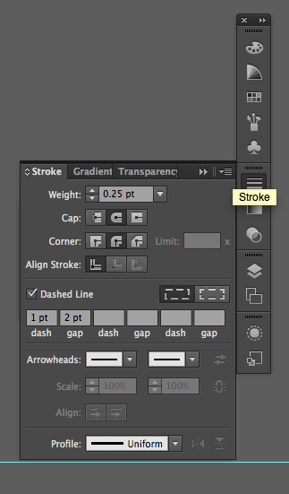
Within the STROKE PANEL you will notice a "Dashed Line" option box. With the "hidden" layer selected, make a dashed line with a 1 pt dash and a 2 pt gap. For the "construction" layer contents use a 2 pt dash and a 4 pt gap.
- Dashed Line Option
Adding Text
The finally step is to reference the cut annotation lines to the drawings that they describe.
Use the T ype Tool by either selecting the icon from the left tool bar, or simply typing t .
Now you can manually type letters or numbers to indicate the cut lines. After typing, press esc to exit the TYPE TOOL and move the type appropriately. Make sure your SMART GUIDES are activated for easily aligning your text to objects. You can turn them on by either selecting "Show > Smart Guides" from the top drop down menu, or simply pressing Control + u .
- Final Drawing
Common Problems
- When I exported my drawing to Illustrator, it seems like it's at the wrong scale? (Either too big for the artboards or too small to see.) Where might I have messed up the scale?
- First, check to make sure you are in the right units in Rhino. Check Options to look at the units. Also double check a certain line in your drawing by using the Distance command to see what units and length appears in the command box. Once you are sure your linework is at the correct scale, make sure you export using decimals and not fractions. For example, when exporting at 1' = 1/4" scale, type in "0.25" inches.
Additional Resources
- Digital Toolbox - Section Drawing
- This is a video tutorial showing how to create the section cut, associated view and Make2d for a section drawing.
- Creating a Clean Drawing from a 3d Model
- This workflow is very similar but focuses on creating architectural section from a 3d model of a building design. Some elements, like the use of poche and the addition of structural details, defer from this abstract section drawing workflow.


