|
Composite Axon Drawing of a 3d Massing Model |
|
|---|---|
| Screenshot |
|
| This workflow shows how to use a 3d model to create a 3d axonometric drawing composed of linework and a rendered image using Rhino Render. This is a simple process to visually articulate the spatial forms inside an abstract double negative model with shadows as well as proper lineweight hierarchy for axonometric drawings. | |
| Uses Tool(s) | Rhinoceros , Illustrator CS5 , Photoshop CS5 |

Steps
This workflow we are using this file: Axonometric Example .
1. Set up the axon view
To create your axonometric view in Rhino, first activate your Perspective viewport. Right click on the viewport name and select Viewport Properties from the drop down menu. In the Viewport Properties options box, select Parallel projection.

It is always good habit to save your view when exporting linework. To create a saved view port in rhino:
- right click current view window left-up corner, choose set view-named views ;

- within the next pop-up window, left click save , then give name to this view-port. For instance, this view called axon


And also in this file, layers have been created as followed:
- Lighting : has a rectangular light for next rendering step;
- Outline : would include outline of this geometry for make2D step;
- Planer corner : would include edges when two or more surface touching each other;
- Hidden line ;
- Model ;
2. Rhino default render for background image
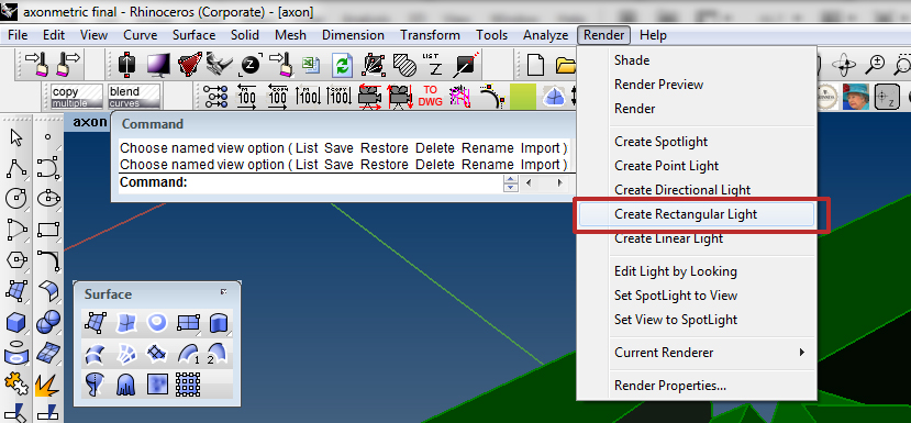
- We are using rhino default rendering tool to get spatial form with shadow and depth. Setting up proper Lighting is very crucial for all different kinds of renderings, no matter what render engines we use. Under render tab in the top tool bar, we can find several kinds of lighting. We can get general ideas from these lights' names. In this case, we use rectangular light;
- left click one corner of the view port, then click another side to determine the length and width. Here F8 is the shot-cut for turn on/off ortho;

- As rhino default setting, this light would be place in the World Cplane . Use move and type v to vertically moving this light;
- Make sure light cover and higher than the object;

- Then go to render-render properties to reset render parameter:
A: Resolution determine the size of your image. DPI means dots per inch when computer calculates the render image pixels. So the higher resolution and DPI setting, the clearer picture would be. But also take more time for render.
B: Under ambient light , we can change the color for light and bottom part. Here we just use light gray for color , dark gray for bottom color .
C: Make sure check the
transparent background
. So after we save the image as PNG, we can get a transparent background which would be beneficial for post-process like editing in the photoshop;


D: Render it. Render icon as followed:
![]()
- save the render. Under File - save as . Save it as PNG format, so as we talked before, the background would be transparent. It will probably look like this:

3. Make 2D
We have already talked about make 2D before, there are several issues have to be paid attention, when we are doing make2D process:
- When we make 2d , make sure in the proper view port. For instance, if doing a plan, we should be in the top view; if doing a elevation, we should use left/right/front/back view and etc.
- Make2D also can be used for a specific perspective view. But sometimes the view would be distorted, if the perspective view is too wide.
- After we select the object and use make2D , we will get the following pop-up window. Under Options , we can check Show hidden lines , if we want to. We can check Maintain source layers , otherwise, we have to put visible lines and Hidden lines to specific layers.

- keep clean layers organized. This would be very helpful when we edit in the AI, because when exporting to AI, the same layers would be kept.
- Always remember to clean the lines before exporting. In this case, outlines of this geometry have been put to layer outline ; planer lines have been put to planer corner ; Hidden lines should stay in hiddenline .

- After clean the lines, we are ready to export. select these line works, go to file-export selected-choosing Adobe Illustrator ;
Then we get this pop-up window,
Snapshot of current view
means the size of the line works would be determined by the proportion comparing with rhino view-port when we exporting them;
Preserve model scale
means we can get a specific size.


4. Use Photoshop to revise render image
As post-process for a axonometric drawing, photoshop is the first step. Considering this render image, which we basically make it all gray, so I will suggest two tool in PS to make it look nicer.
- Open final render PNG file in the photoshop. You will find the background pixelated, that means the background is transparent.
- Go to top tool bar-under image-adjustments-levels . This tool basically is used to create high/low contraste image, which means make white part looks whiter and make black part looks blacker.
- After get the pop-up window, we will find three triangular icons: one is black, one is gray, one is white. Move the black one to right will cause the dark part of this image darker; move the white one left will cause the light part lighter.
- If we press the Auto icon in the right part of this window, computer would automatically help us to equally divide the black/gray/white color to different levels. But depends on different image and personal taste, so this Auto doesn't always work.


- Another tool called brightness/contrast. Go to top tool bar-under image-adjustments-brightness/contrasts . This tool creates a similar effect.


5. Use AI for organizing proper lineweight hierarchy
AI file can be found here .
- Open AI file, go to artboard tool to change the size of the workplace.
- As last week's exercise, ctrl+A select everything, then put them in the middle of the workplace.
- Drag the final render image into AI, press embed icon in the top tool bar. In AI, images can be linked, or embed. Link means image is just a place holder. When we change the outside image, this link would also be automatically refreshed. But if we move to image for instance to another folder, or we save the AI file in another computer, then this link doesn't work. So in this case we just embed the image.

- Use the corner box to scale the image to fit for the line work. Pressing Shift helps scale the image in a certain ratio.

- As the architecture drawing, line weight is very crucial. In this case we select outlines changing to black, continues line, 1.5pt, planer lines to dark gray, continues line, 0.75 pt, hidden lines to light gray, dashed line, 0.5 pt.


- The final result can be download here .
- Now we are ready to save as PDF and print.
6. Export as PDF
