|
Organizing Detailed 2d Drawings in AutoCAD and Illustrator |
|
|---|---|
| Screenshot | |
| This workflow will demonstrate how to create multiple scaled viewports in AutoCAD as a means of showing varied level of detail. As a designer, this is important to know for conveying design intent. The workflow will also show how to add basic annotations and dimensions to your drawing and then import it into Illustrator for post processing. | |
| Uses Tool(s) | AutoCAD 2012 , Illustrator CS5 |
The files used in this workflow can be found here: Workflow Week 7 Materials
Step 1: Start with a Detailed 2d Drawing
For this workflow, we will be working with a existing detailed plan drawing of the second floor of a house. As you can see, there is a lot of information provided within a single drawing that will be important for conveying design information and intent.
Step 2: Creating Multiple Scaled Viewports
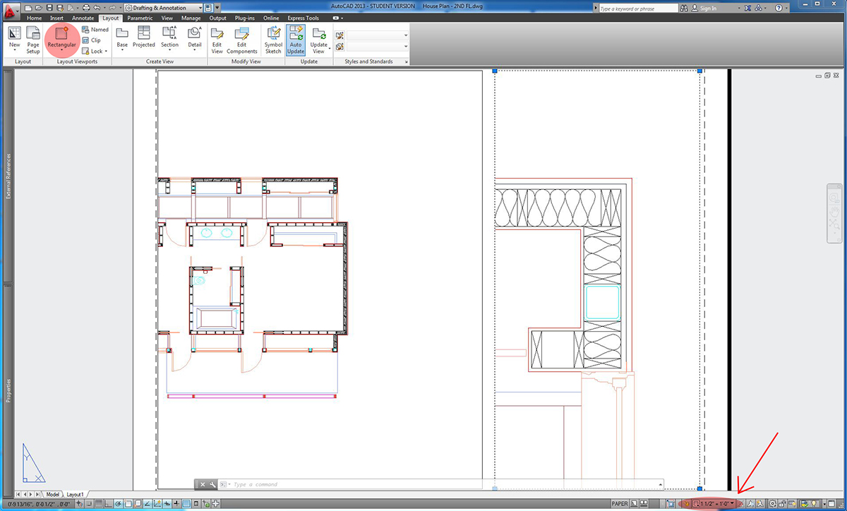
In Paperspace, you will create two viewports at different scales. One will show the east facing end of the plan at 1/8"= 1' and the second will show a detailed view of the northeast corner of the plan at 1 1/2"= 1'. The goal will be to display a general level of detail at 1/8" scale and a high level of construction detail at 1 1/2" scale.
Note: When you find a viewport layout that you are satisfied with, you can "lock" the viewport so that you do not accidentally make changes to it. To make further changes later on, simply unlock the viewport to modify the display or scale.
Step 3: Adding Annotative Text
We will add some text to the drawing to give it contextual information. Move back to model space. Click the small arrow at the bottom right of the Text palette to bring up the Text Style Manager and check the box for "Annotative" under size. When you set text or dimensions to be annotative, you are designating a consistent size for the text to be displayed in paperspace. This maintains uniformity in how the text size will display in paperspace when you have multiple viewports at different drwing scales. Set the text height to 1/8". When you hover over drawing elements such as text and dimensions that are annotative, the small blue symbol designating them as such should appear.
On a designated text layer in model space, create text using the "Single Line" or "Multiline Text" commands under the Text palette of the "Annotate" ribbon. Place a text label designating the "Master Bedroom" and "Master Bathroom".
Step 4: Adding Annotative Dimensions
Next, add some overall dimensions to the building, but also some more specific dimensions that locate the structural column in relation to the finished exterior wall and the window in our detailed plan view.
Assigning annotative properties to dimensions is similar to text and has the same effects in paperspace. Click the small arrow at the bottom right of the Dimension palette to bring up the Dimension Style Manager and either select Annotative dimension style, or select "New" and create a copy of the Standard dimension style. Title this layer "Annotative" and be sure to check the box for "Annotative" in the options dialogue. Set the text height to 1/8".
On a designated dimension layer in model space, create dimension annotations using the "Dimension" command under the Dimension palette of the "Annotate" ribbon. You can add linear, aligned, angular, and radial dimensions based on your drawing. If we know that some of the dimensions are going to be associated directly with the 1 1/2" detail plan, we can set the drawing scale to 1 1/2" before drawing those dimensions. That way they will since we are using an annotative dimension style they will be set to the appropriate size in paperspace.
Step 5: Displaying Detail in Layouts
Now that we have added the appropriate text and dimensions to the drawing in model space, we will move back to the Layouts that we created in paperspace to modify what information we would like to display at the various scales. This is an important step in creating legible drawings that are to convey a specific design intent.
At 1/8"= 1', the detail within the wall cavities becomes a bit confusing and muddled. For clarity, we will turn off some of these details that we do not need to see at 1/8" but would still like to see at 1 1/2". (If we were to turn off the layer from model space, it would not show up in either view).
Open the Layer Property Manager from the Layers tab. Double click in the viewport that you would like to change layer display within, which in this case would be the building plan viewport at 1/8" scale. Once the viewport is active, find the layers that you would like to turn off and click the icon under "Freeze VP". We will turn off the A-WALL-HATCH layer as well as the S-COLUMN layers, leaving only the exterior lines of the walls visible.
Step 6: Displaying Annotations in Layouts
When working with multiple scaled viewports, it is often not enough to just make text annotative, especially if you would like some text or dimensions to display only at one specific scale in paperspace.
For our drawing, we only want to see the dimensions at the corner of the building displayed in the 1 1/2" scaled viewport. In model space, under Annotative Scaling tab in the "Annotative" ribbon, click the "Add/Delete Scales". Select the dimensions at the northeast corner of the building and press enter or spacebar. A window will appear that will then let you delete the annotation scale for 1/8"=1'. Now these dimensions will not appear in our 1/8" viewport.
Let's also add a little more information to the plan detail. You can use the “Leader” command to create text annotations with an associated arrowhead leader. Add leaders outside of the floor plan where we set up our detailed view calling out "3/4" WOOD SIDING", another for "1/2" GLAZED ALUMINUM FRAMED WINDOW", and one more for the "4" STEEL TUBE COLUMN".
Note: While you always have the option to create different dimension styles for different dimension scales, creating annotative dimensions from the start and Adding/Deleting visibility scales is a much more efficient way to maintain a working drawing. It allows you to easily modify text and dimension scales at a later date should they change.
Step 7: Importing a DWG to Illustrator
In AutoCAD Part I you learned how to plot from DWG to PDF. Very often as design students and also as professionals, we would like to modify or add more post-processing information to a drawing rather than just showing line work. While you can import a PDF plot directly into Illustrator, since Illustrator is not a universal PDF editor, there are limitations with how much you are able to modify.
Illustrator is able to import DWG drawings and will even recognize layers and layout scales while doing so. Be sure to save your drawing down to an AutoCAD 2004 format before importing to Illustrator or some attributes will not display. AutoCAD will not recognize viewport boundaries, however. Therefore, when you are bringing a DWG with multiple layout viewports into Illustrator, similar to what we have set up for our house, you will have to save the drawing as a separate DWG file for each viewport that you would like to work with in Illustrator, and then bring them together into a single document within Illustrator. You can do this by making a copy of the Layout and deleting one of the viewports on each Layout before saving the files. For our purposes, we will only import the 1/8"= 1' building plan.
When you have a layout set up in AutoCAD, you can select it from the drop down tab in the "Layout" option of the dialogue box. When importing a Layout from CAD, remember that paperspace scaling is always 1:1, so you will want to make sure that the scale factors in Illustrator are also set to 1 Unit = 1 Inch.
Step 8: Modifying Lineweights and Adding Texture
While Illustrator will maintain source layers from AutoCAD, you will have to modify the line weights. If you have done a good job of assigning lines in the drawing to appropriate display layers, this should be a simple and easy task. To review this process you can refer to this workflow: Cleaning Up 2d Drawings Extracted from a 3d Model .
The Illustrator file "House Plan - eighth scale.ai" included in this week's workflow materials already has our 1/8"= 1' layout imported from AutoCAD.
You can see that the layers that we were working with in AutoCAD have also imported into Illustrator and have already been adjusted according to desired line weights.
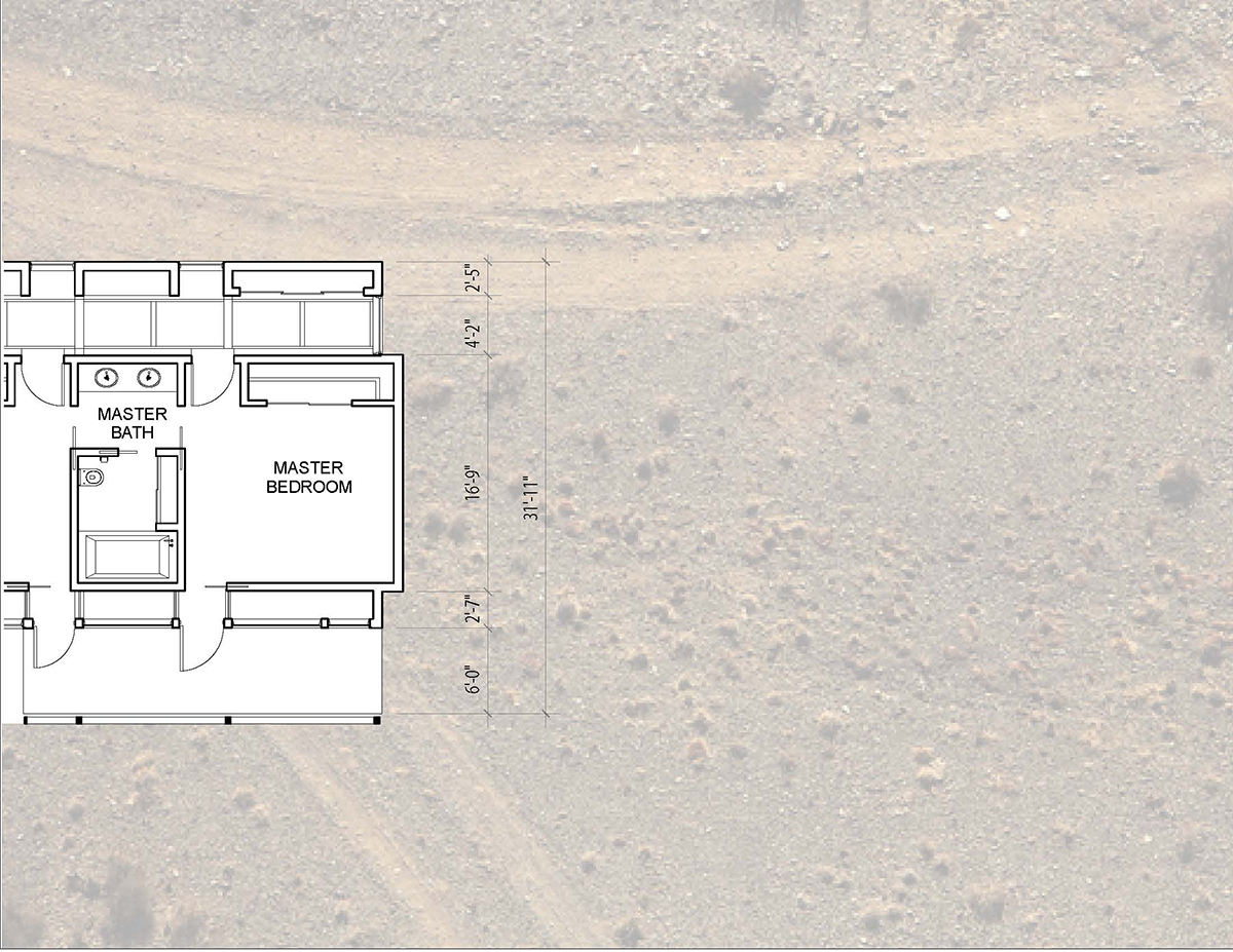
Now we can add some site texture to give the building plan drawing some context and contrast on the page. Once you find a ground texture that you are happy with, place them into the Illustrator file on separate layers and make sure they are set behind the AutoCAD layers at the back of the drawing. You will have to make a clipping mask for the ground layer that follows the shape of the house so that the interior of the plan has a white background and only the context surrounding it is textured.
The final drawing should look something like this.


