|
3d Massing Models : 3 Different Ways |
|
|---|---|
| Screenshot | |
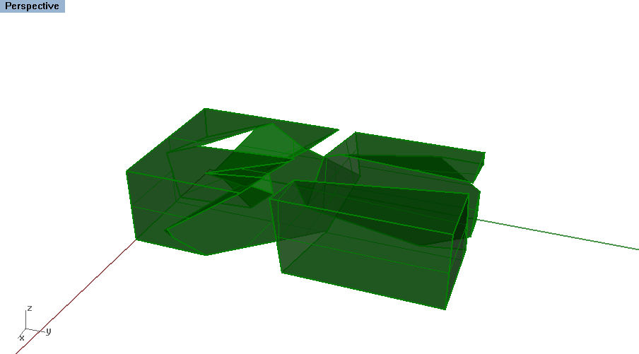
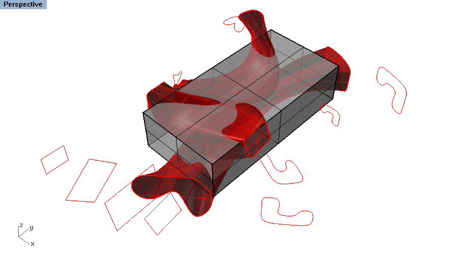
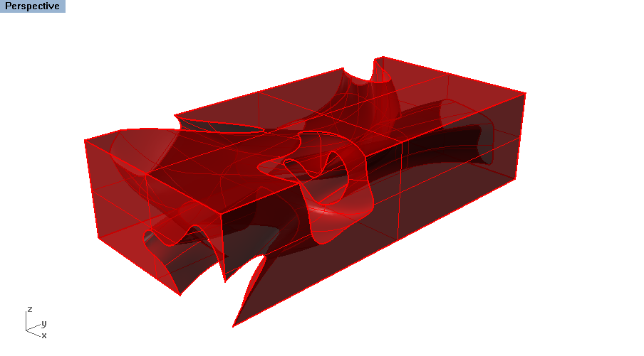
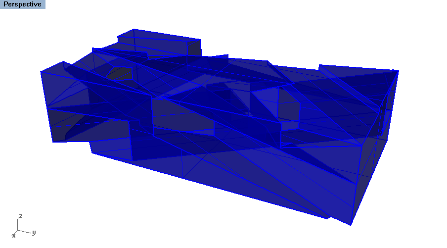
| This workflow will showcase three different modeling strategies for creating abstract models exhibiting double negative space. These three different methods cater to different surfaces tools in Rhino as well as different formal and spatial strategies. One method focuses on using solid geometry, one method focuses on created curvy lofted forms and the last one focuses on creating extruded volumes from existing linework. | |
| Uses Tool(s) | Rhinoceros |
There are many ways to begin modeling in Rhino. This workflow goes over three different basic ways of modeling: working with solid geometry, lofting to create curvy surfaces and extruding to create rectilinear geometry. Each method creates a different type of geometry that may cater to different spatial or formal systems. Often when creating a very advanced Rhino model, numerous modeling methods will be used to create the overall form.
Steps
Creating the Original Cube
Open a new Rhino file and set the Units to Small Objects - Inches. We will be working in all four viewports throughout this workflow.
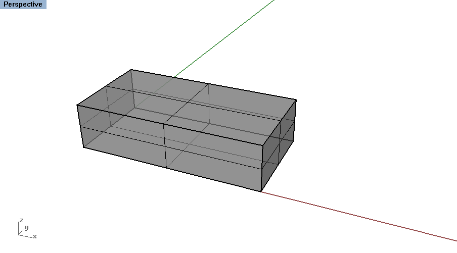
To create a cube, use the Box command. It will prompt you in the command line for the first corner - type in the origin. Then enter the length, width, and height as follows: 4", 16", 8".
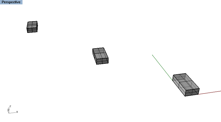 Copy
this geometry two more times in a diagonal. This way, we can use the Top + Right view to see each box individually as we proceed with creating spaces inside them.
Method One : Using Solid Geometry
This method is the most inexact as it does not involve working with curves but instead with creating geometry in the same manner that we created the original cube. On the other hand, this is also the easiest method as the geometry begins as a pure, rational surface and will easily subtract from the cube in the final step. This is also an ideal method for those who may be working with an aggregated collection of similar objects such as cubes or spheres.
Creating Solid Geometry
Before creating new geometry, click on a new layer and titled this "Solid".
To preview the variety of solid geometries available, hold down on the Box icon on the left toolbar. You can also see the list under the Solid option in the top toolbar.
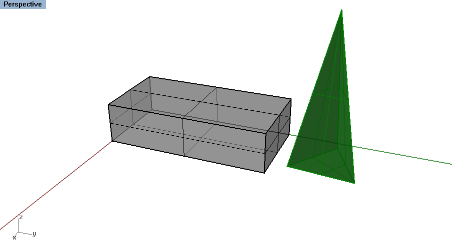
Click on one of the options, such as Pyramid . Each of these solid surface geometries has different inputs that can affect the overall form you create and HOW you create it. For example, with Pyramid , you can edit the number of sides or create a star rather than polygon base. To chose one of these options, either click on the option or type in the underlined letter.
Create one object out of the geometry of your choosing, making it similar size to the original cube.
Editing + Moving Solid Geometry
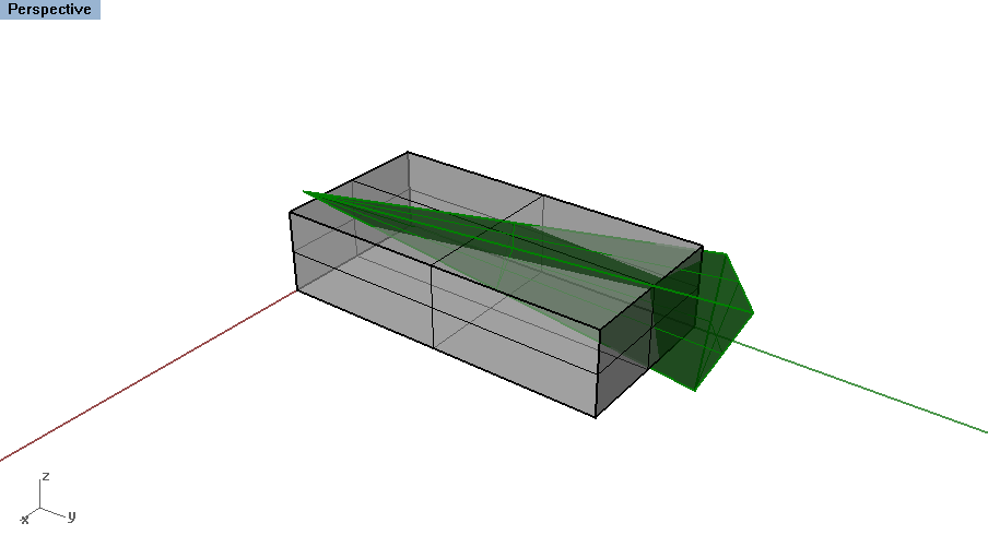
To make a evocative form, this geometry must interact with the original cube. Use the Move and Rotate3d to place the object so that it intersects with the cube.
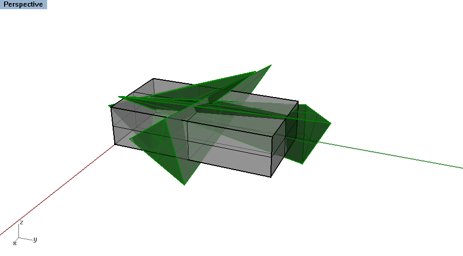
Copy the form and place the copy in a different area on the cube. Again, Move and Rotate3d tools to place it in a different position to interact with the first form. Repeat this step until approximately half the cube volume is filled with new geometry.
Boolean Difference
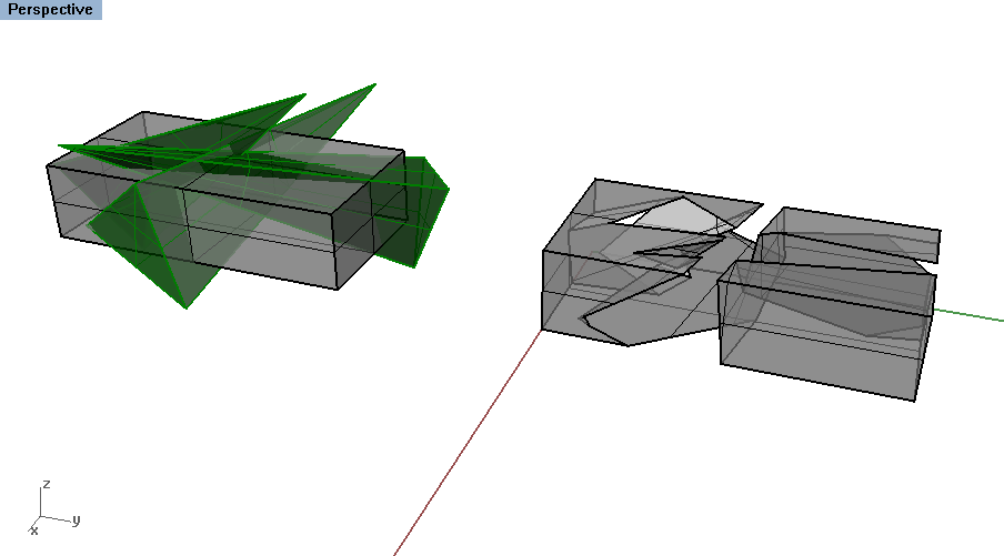 Prior to voiding the cube, copy the overall form you have created so that you can return to the previous step. After performing the Boolean operations, you cannot return to the original forms. Always keep a copy of the formwork before the next steps in case you later want to redo, move or edit a piece.
Now we will subtract one object at a time from the cube. Use the BooleanDifference command. It will prompt you for the first set of surfaces or polysurfaces. Select the original cube and press enter. Then select the forms you just previously created (everything except the cube) and press enter again.
The resulting form should be the cube minus all the intersecting volumes from the geometries you created. You should now have a finished example of the first method - using solid geometries.
Method Two: Lofting Curves
This curve based surface modeling method is ideal for creating curvy forms. Loft is a popular surface tool that can create forms based on a series of section curves that are connected together, either by a smooth curve (therefor approximating the geometry) or straight surfaces.
Create Construction Curves
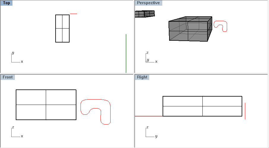
Move to the second cube created in the first step. Change to a new Layer titled "Loft".
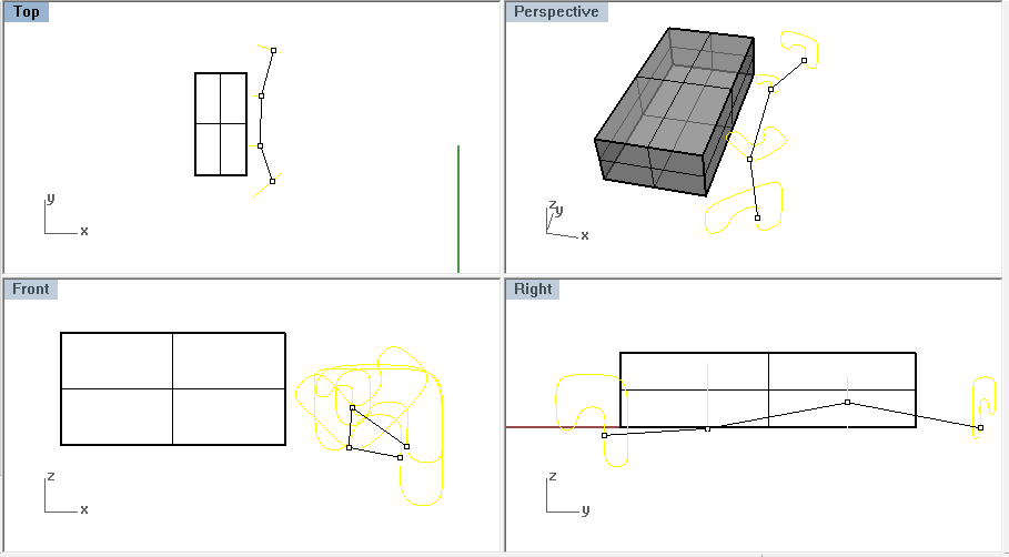
Create a Curve in the Front view. Make a closed curve so that the resulting geometry will also be closed. When drawing in the Front view, your linework will be created along the y-plane so Move the object alongside the Cube.
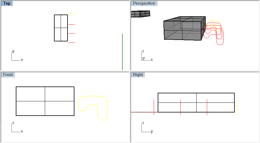
Copy this geometry three times along the length of the cube.
Edit Construction Curves
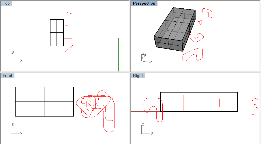
Rather than keeping the section curves exactly the same, use the Move , Rotate and Scale commands to edit the curves to create a more curvaceous shape. Rather than working in the Perspective view, edit each form in the Top, Front and Right window.
Make sure to keep the curves planar. This means, all the points on the curve are in the same plane.
Loft the Curves
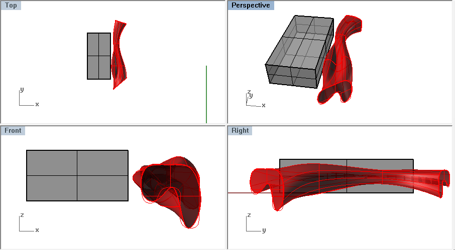
Type the Loft command and select the curves in the order from one end to another. The order in which you select the curves is important! Then press Enter.
The first prompt will ask you to adjust curve seams. The seam should connect the curves in the easiest manner. If the seam juts from opposite ends along the curves, then click on the point and move it. Click enter to move on.
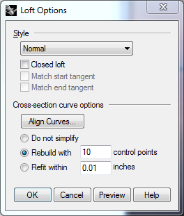
The Loft menu will show up, allowing for different ways to connect the section curves. At any moment you can preview the geometry. Preview the difference between Normal, Loose and Tight fits - which can affect how closely the loft fits the construction geometry. Select which option you prefer and press enter.
Move + Cap the Lofted Geometry
Cap the lofted geometry so that it becomes "solid". A trimmed planar surface will cover both ends.
Move the closed polysurface so that it intersects the Cube. Notice that the construction geometry is not attached to the final lofted form. Keep the linework in case you want to remake the surfaces later on.
Create another form on the other side of the cube so that the two lofted forms intersect the cube and each other. Try working in a different direction by creating closed section curves in the Right view.
Boolean Difference
Before proceeding with the Boolean command, Copy all the surfaces and curves as a backup. Then Delete the linework so that just the lofted surfaces and the cube are prepared for the next step.
Use the BooleanDifference command again, selecting the cube first and then the lofted pieces. If any of the forms were not capped, then the objects will not Boolean properly.
Method Three: Extruding Curves
In this final form, you will be using curves to extrude a volume to then subtract from the Cube. Rather than using serial section geometry, extrude uses a base curve that is extrude in a specific direction. The extrude command also has various more specific options, such as Sweep1, which we will use in this method.
Create Construction Curves
Return the last cube in the model space and start a new layer titled "Extrude".
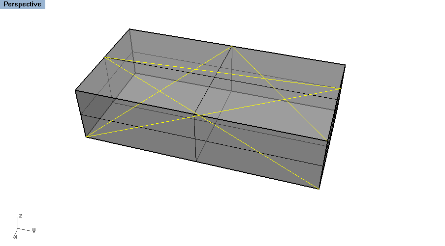
Rather than working in one direction at a time, create a Polyline that moves in all directions inside the cube. Make sure your object snaps are on and use the Perspective view to create a continuous lines that moves around the interior spaces of the cube.
Next, create Rectangle near the start of the previous polyline. Chose the Vertical option to easily create a cross section curve near the start, perpendicular to the rail.
Sweep the Forms
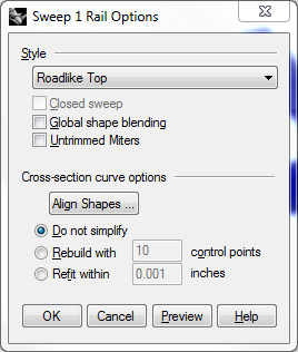
Use the Sweep1 command to extrude the rectangle along the continuous polyline. Rather than using a simple Extrude command, or ExtrudeAlongCurve, Sweep deciphers between the cross section curve geometry to maintain that the form stays perpendicular as it follows along the rail geometry. Select the rectangle as the cross section curve and the continous polyline as the rail.
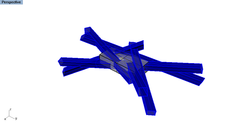
The Sweep menu will appear, previewing your created geometry. Scroll down from the top menu to preview the different options that effect the view from which the cross section geometry is maintained. The final form should be a series of different tubes jutting through the interior of the cube.
Note that all of the objects are not joined, but separate objects. Select all of them and Cap them to ensure that they are closed polysurfaces.
Boolean Difference
Again, prior to using the boolean tools, copy the geometry as a backup and delete the linework so that you are only working with the remaining surface geometry.
Use the BooleanDifference command once more, selecting the cube first and then the remaining capped tubes. While the objects created from the Sweep were separate, the overall negative space continues very clearly from one to another because of the original construction linework.
Additional Tools
All of these methods emphasized the subtraction method : creating surface geometry that was then subtracted from the original cube geometry. At any point, you can go back to the resulting form and add to it. Use the BooleanUnion command to add closed polysurfaces to the object.
Common Problems
- My final object failed to Boolean. What does that mean?
- Boolean operations only work on closed polysurfaces, in which the geometry is understand to fully intersect each other. Check your surface in the Object Properties menu or selecting the object and typing What . Make sure there are no naked edges - where surfaces are not properly touching each other. For more information or help, check the McNeel page here .
- My Sweep object seems incredibly complex, huge and incorrect. What did I do wrong?
- Make sure you are selecting the small, perpendicular geometry (the rectangle in this instance) as the Cross Section Curve and the polyline that crosses throughout the interior of the cube as the Rail Curve . Flipping these can create some very crazy geometry.
Additional Resources
- TU Delft Toi-Pedia
- This wiki entry has a very detailed Rhino entry, with many images showing the different surface commands.

