|
Mapping a Complex Physical Form Using the Triangulation Method |
|
|---|---|
| Screenshot | |
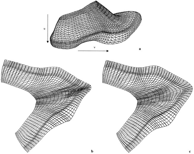
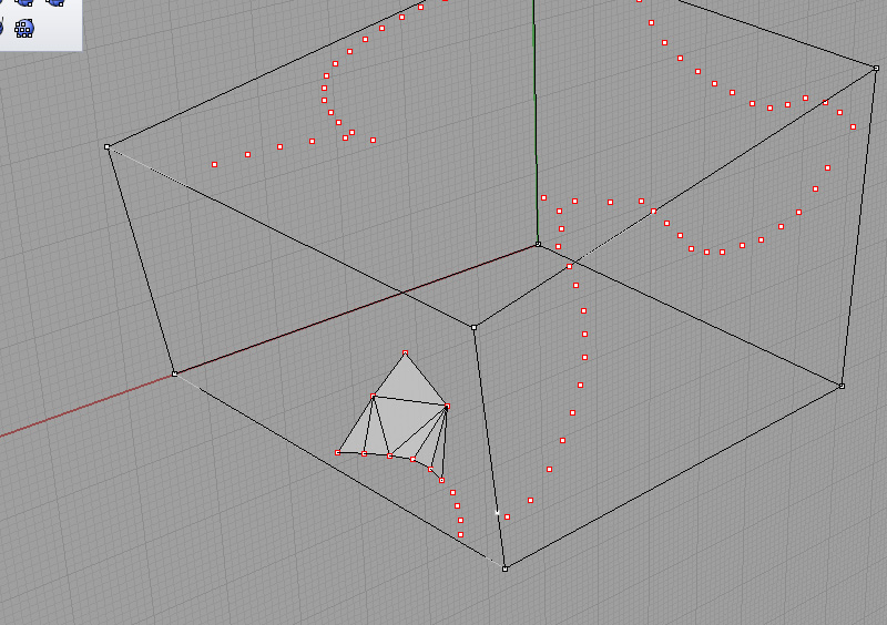
| This workflow presents a method for modeling a complex plaster surfaces in 3d by first mapping an ordered grid points on the plaster, then transferring these into Rhino3d, and finally connecting these points into a triangulated mesh surface. | |
| Uses Tool(s) | Rhinoceros |
Steps
Inscribe Points on Planar Surfaces
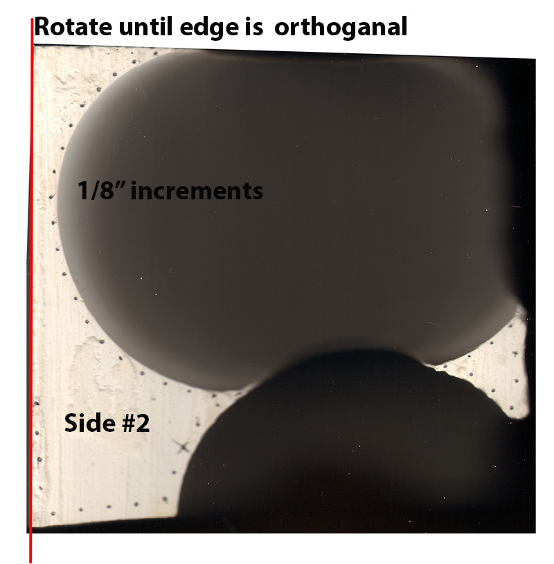
On each planar surface of the plaster model (those surfaces produced by the a side of the mold or a cut), note the curved lines that result from intersections with non-planar surfaces (those surfaces produced by the balloons). Along each of these curves, inscribe points spaced at 1/8" increments. Each inscribed point should be on the planar surface, but as close as possible to the curved edge without causing the plaster to crumble.
Scan Planar Surfaces
Now that we have inscribed our plaster model with reference points that lie on planar surfaces, we can use a scanner to produce accurate images of each face that will allow us to extract the geometric information we need.
Using a sheet of clear acetate to protect the scanner glass, scan each flat face of the plaster model.
Process Images
The images we have taken of our plaster model now need to be processed in Photoshop - cleaned, straightened, and cropped - before moving them into the CAD environment of Rhino.
In Photoshop, use the ruler tool to set one of the edges to be orthogonal. You might need to increase the canvas size so that you do not lose any information. Once you have an edge that is orthogonal, crop the image to the scan of your form.
Label each side with a number (use pencil and write it on the form itself)
Create a 3d Wireframe of Planar Faces in Rhino
Before extracting geometric information from our scans, we will need a good system of reference positions which will help us to orient things properly.
Using a ruler, take the relevant dimensions of just the planar faces of the plaster model. You may want to make a quick dimensioned sketch at this point. Next, produce a 3d "wireframe" model in Rhino of these planar faces, using only lines and polylines to construct the relevant non-curved edges.
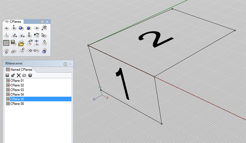
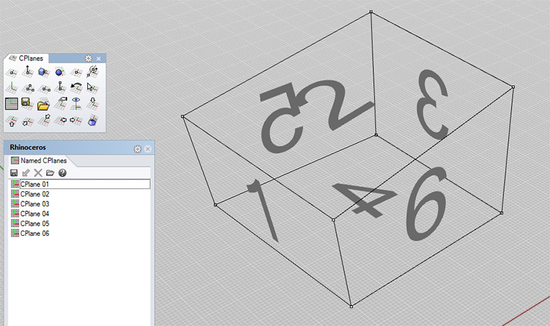
Orient the c-plane appropriately as you work. When you are finished constructing the wireframe, create a "named c-plane" for each planar face of the plaster model. There should be seven of these in total - 6 outside faces and your section cut.
Place and Orient Images in Rhino
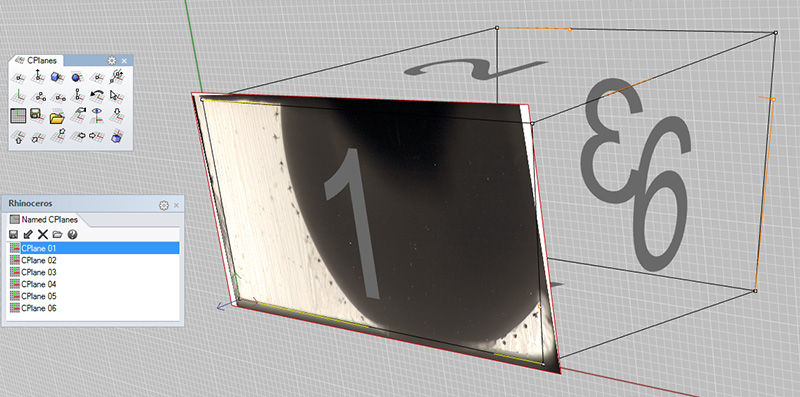
Using our wireframe model as a guide, we may now position the cleaned-up images of the flat faces of our plaster model in their proper locations in 3d space.
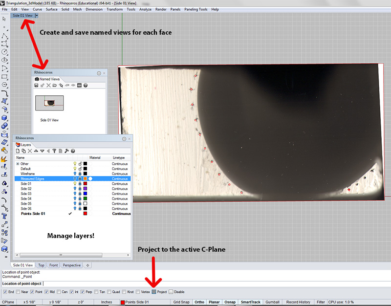
Making the appropriate c-plane active, use the "pictureframe" command. Then "scale 2D" to your measured edges. Things may not line up perfectly at this point. That's okay - this is a very approximate mapping process. Since we've already built the 3d wireframe in Rhino in such a way that everything matches up, we should let the wireframe remain the same, and nudge the placed images around a bit until things generally look right.
Extract Geometric Information from Images
With the images properly positioned, we may now transfer the points we plotted in step 1 into the 3d space of Rhino.
Be sure to remain aware of which c-plane is active during this process, and to be sure to work with the "project" snap active. This will ensure that all the points you have mapped lie on the same plane.
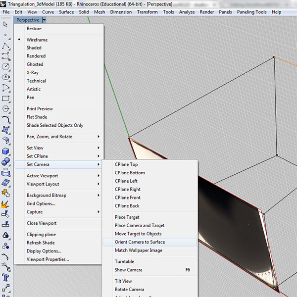
If you have non-orthogonal cuts then you will need to create custom views to place points. Set a camera by orienting it to the surface (you can select the PictureFrame you have imported as the surface upon which to orient the view).
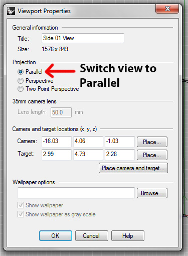
Then change the view type to "Parallel" to minimize distortion and maximum placement accuracy.
Save the new view and place points where indicated on the image.
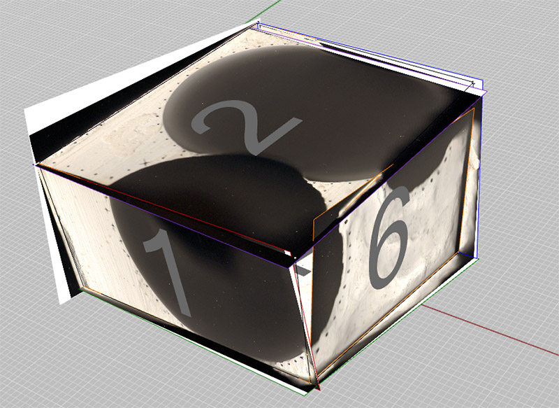
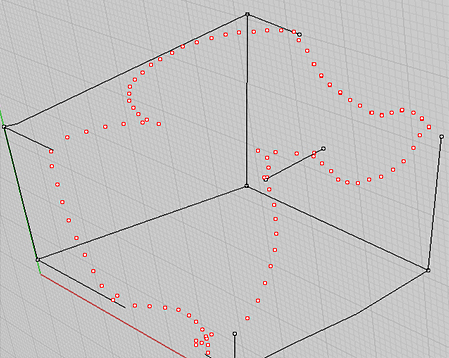
After doing all sides like this your model should contain this amount of information:
Inscribe Points on Non-Planar Surfaces
Our model is starting to take shape in rhino, and we can now begin to imagine the curves that describe the edge where each of our concave surfaces meets one of the planar plaster faces. To describe the inner surfaces of each of these concave forms, we'll need to plot more points.
Working on one concave surface at a time, inscribe a set of points on each of the non-planar surfaces of your plaster model. We'll refer to these points in future steps as 'non-planar points'.
Skimming ahead, you'll see that limiting the number of points to the minimum required to visualize the surface will save you a great deal of time and headaches... but don't be too frugal. You'll want to inscribe enough points such that the overall shape of the surface is approximated well, and that any important features, such as a hole where two adjacent forms intersect, are preserved.
Collect Measurements
For each point we've mapped onto a non-planar surface, we will need to collect and record measurements that will allow us to plot a corresponding point in rhino.
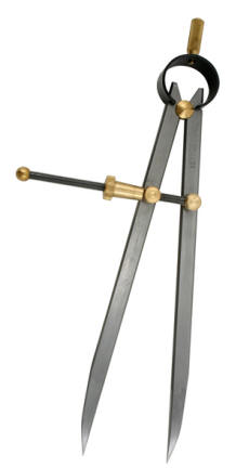
Using a measuring compass (also called a divider ) and ruler, measure the distance from each of the non-planar points (those you just inscribed) to any three of the planar points (those that lie on the planar surfaces of the plaster, and that we have already mapped into rhino). Taking measurements in this way is one of the standard uses of the measuring compass .
Depending on your particular geometry, you may find it advantageous for most of these measurements to be taken from the same set of three planar points - for example, planar points near the corners of your model. This will simplify the recording and re-plotting process. Ideally, all of the non-planar points for a given surface will take measurements from the same set of three planar points, but this may not always be possible.
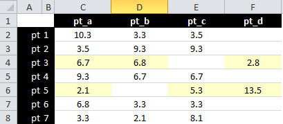
If you're familiar with MS Excel, this may be a good time to break out a spreadsheet, as seen below. In the screenshot below, measurements from most of the non-planar points have been taken relative to the same three planar points: pt_a, pt_b, and pt_c. But for two of our non-planar points, these measurements were impractical, so pt_d was used instead.
Record distances for all points inscribed on a non-planar surface, and then proceed to next step.
Plot Non-Planar Points
Now that we have collected positional information regarding each one of our non-planar points, we can now use this information to create 3d points in Rhino that will approximate the surface of our plaster model. Since we know the distances of each point in question to a small number of reference points, we can do this through a series of intersection operations in Rhino.
Using the corresponding rhino point as a centroid, make a "sphere" with the radius = distance. Do this for all three planar points.
Select any two of the spheres and type the "intersect" command. This will result in a circle describing the intersection of these two spheres, which may now be deleted. Next, select the circle that was just created and intersect it with the remaining sphere. This will result in two intersection points, one of which will lie on the desired surface (it should be obvious which is the right one). Delete the circle and the unwanted point.
Repeat these steps until each void surface is well-populated with points. This will take some time.
Construct Mesh Triangles
Once you have enough points mapped, you can begin creating a surface from the points. We'll do this using the "3dFace" command in Rhino, connecting the points one triangle face at a time.
Common Problems
Once you have started mapping points and triangulating them into surfaces, the surface will inform you about where you need more information. It should be equally refined along the surface you are mapping. If you have areas of density and areas of sparsity, then you need to map more points in the sparse areas.
Resources
Online Rhino Help Guide : This guide is incredibly helpful with animations showing the different Rhino commands.
Rhino Books and Tutorials : A slew of resources for Rhino.
