|
Creating a Shadow and Linework Rendering |
|
|---|---|
| Screenshot | |
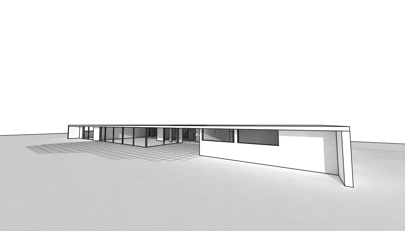
| This workflow uses V-Ray for Rhino to light and render a model, emphasizing shadows, adding additional linework elements in Adobe Photoshop and Illustrator. Emphasis will be placed on creating a well lit rendering using appropriate settings in the render engine and sunlight system, as well as taking care to properly save views to ensure seamless match of rendered image and extracted 2D linework. | |
| Uses Tool(s) | Rhinoceros , VRay , Photoshop CS5 , Illustrator CS5 |
Methods covered in this workflow:
- Saving Named Views in Rhino
- Adding a Sunlight System
- Adjusting Options Settings in V-Ray
- Rendering with Shadow
- Extracting 2D Linework
- Working in Photoshop and Illustrator with Smart Object Layers
- to follow along with this workflow, download the Rhino file here
Shadow and Linework Rendering
This workflow uses V-Ray for Rhino to light and render a model, emphasizing shadows, adding additional linework elements in Adobe Photoshop and Illustrator. Emphasis will be placed on creating a well lit rendering using appropriate settings in the render engine and sunlight system, as well as taking care to properly save views to ensure seamless match of rendered image and extracted 2D linework.
Steps
Step 1: Saving Views in Rhino
Adjust Camera Settings
The first step toward creating any rendered image is to adjust the camera within Rhino to the settings that are appropriate for a particular shot. To adjust the camera focal length in Rhino, select the viewport menu by clicking on the viewport dropdown menu > "viewport properties" along the top of Rhino, or from the viewport itself. Here you will find an option called "Viewport Properties" which will allow for customization of camera lens focal length.
The smaller the number for the focal length, the wider the camera angle of view. The larger the number, the tighter the viewing angle. When adjusting the focal length, keep in mind what it is you are trying to frame in the shot to appropriately capture in the view.
Setting Camera Position
Once the camera adjustments have been made, the position of the camera can be set for the exterior renderings. Orbit around the 3D model to find a suitable position that effectively shows the elements that will be captured within a particular rendering.
Saving Views
Once a satisfactory camera position has been found, you can save this view so that you can always return to it in the future. This is helpful when trying to find the right viewing angle without losing previous view information, and when creating renderings with layers of information such as overlaying linework. It is important that the views match precisely in order to layer different renderings or model information together.
In order to save the view go to the viewp dropdown menu > set view > "named views..." Here you can save multiple camera positions to return to at any time.
Step 2: Lighting
Creating Sunlight System
In order to illuminate the model environment, a source of sunlight needs to be created in the Rhino model using V-Ray Sun. The sun will allow for setting both the time of year and time of day, as well as the model's global location. To create a sunlight source go to the render dropdown menu > panels > sun or select the sun icon from the V Ray toolbar.
Changing Sunlight Settings and Location
The times of day and year that are chosen will effect the quality of light that the sunlight system provides for the model. Early in the day and late in the afternoon provide less harsh light and more dramatic shadows. In order to change the settings, deselect manual control and set the time of day and time of year appropriately for a particular atmosphere to be created through the sunlight. Also select the global location of the model to get the proper lighting conditions. (In the case of the sample file, this house is located in Los Angeles, California.)
Placing Sun
Now that the settings have been made, click okay at the bottom of the sun settings dialogue. You will now be able to click anywhere in the viewport window to place your sun. Once the Sun is placed, a large, wireframe arrow will appear in the window. This illustrates the position and angle of the Sun.
Step 3: Setting Render Options in V-Ray and Rendering
Overriding Materials
The V-Ray Options menu will allow for more detailed specifications to be made for the rendering process. In order to change those settings, you can find the options dialogue either by going to the V-Ray dropdown menu > Options or by clicking the Options Icon in the V-Ray toolbar, a tag with the Capital letter "O".
Once in the Options dialogue, the first settings that can be changed to allow for a neutral palate of materials is to expand the global switches setting in the dialogue and select override materials and change the color of the material to white. Doing this will privilege the shadows in these renderings, rather than having any material color distractions.
- tip - when rendering with all opaque materials, it is best to turn off the layer that glazing has been modeled on so that light can still penetrate the building. This will effectively render without glass while still giving the effect of a transparent material.
V-Ray Camera Settings
The camera settings in V-Ray act just like a physical camera does, with shutter speed, f-stop (aperture), and film speed/ISO settings to allow for a nuanced control of the rendered image in partnership with the light sources. Expanding camera in the options dialogue and making sure to select physical camera on will allow you to change the settings of the aforementioned aspects.
- Shutter Speed
- lower numbers mean longer exposures and higher numbers mean faster exposures. Longer exposures are good for lower amounts of light (sunrise, dusk), while shorter (faster) exposures for more light (mid-day Sun, brightly lit interiors).
- F-number
- F-number, or aperture, is how open the lens is and how much light it then "develops" in your rendering. The higher the f-number, the smaller the aperture opening and the less light it takes in. These f-numbers are good for conditions with a lot of light. The lower the f-number, the larger the aperture opening and the more light is taken in. These apertures are good for low light conditions.
- Film ISO
- The ISO is the film speed and determines how sensitive the "film" is to light. Lower ISO numbers like 100-200 are good for bright light conditions. Higher ISO numbers like 500-1200 are good for lower light conditions.
White balance can also be controlled in the camera option. Once you begin rendering, you can check to see if the rendering has a yellow or blue cast from the skylight. Depending on what color is being cast on the model, you can bring it back to white by selecting the color swatch next to white balance and either choosing a slightly blue or slightly yellow tint to balance out the color cast by the skylight.
Render Output
The output editor in the options dialogue allows for the specification of dimension of the rendering. The output dimensions are an important factor to consider when creating test renders and moving forward to the final rendered image. Test renders can be small, in order to quickly see the settings and make appropriate changes. Final renderings can be quite large, scaled appropriately to the media that it will be presented on.
Expand the output option, checking override viewport to allow for changes in the aspect ratio and size of the rendered viewport. Whether setting a size for test renders or for the final rendering, make sure to select "Get View Aspect" before rendering to ensure that the viewport in Rhino which you are rendering matches the aspect ratio of V-Ray's options.
Rendering
With the ability to set many parameters for each rendering, there is a process of trial and error in creating the final rendered image. Sometimes the light is too bright, or too dim. The camera settings may not be adjusted to correctly capture the specific qualities of light set, and therefore the rendering process is an iterative and somewhat experimental one. The default camera settings may not be well suited to the light source available in the model, and the camera settings will have to be adjusted accordingly.
- Too Dark
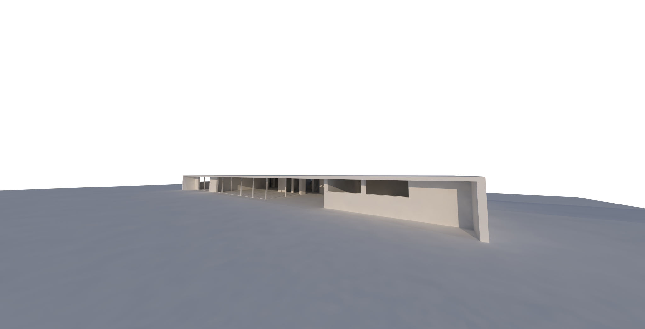
- The camera settings for this rendering are creating a very dark image. Setting adjustments to consider when confronted with a dark image are slowing down the exposure time by changing it to a smaller number, lowering the f-stop, or making the film ISO faster by changing it to a slightly higher number.
- Too Bright
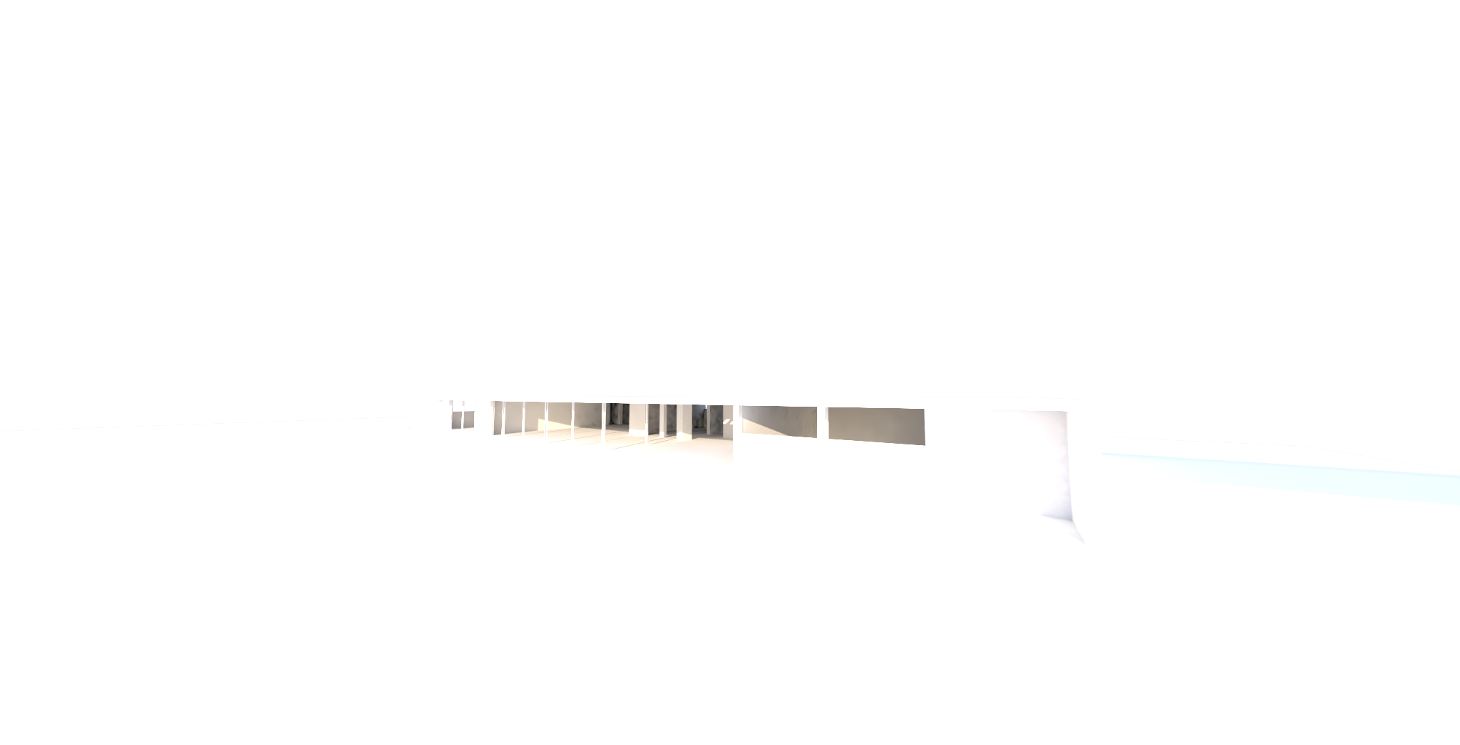
- In this iteration the light is much to bright and is blowing out details in the rendering. The camera adjustments that can be made to try and correct the brightness are to set a faster exposure time, a smaller aperture (larger number), or make a slower film ISO (100-200).
- Well Exposed
- Through trial and iteration, you will find that a combination of camera settings with the light source can produce a satisfying rendering with good exposure, shadows, and highlights.
Once you have achieved this in the test renderings, you can change the settings to create a larger rendering. Remember to adjust the output settings before moving into your final rendering.
- tip : If you have created a combination of settings that you particularly like, you can save settings in the options dialogue by clicking on the floppy disk icon to save. You can then load those settings into any Rhino file that is rendering with V-Ray to duplicate your saved settings. You can also load pre-saved settings.
Step4: Extract Linework
Return to Saved View
Going to view > set view and selecting the saved view used for the rendering, you can now extract 2D linework which will be overlayed onto the final rendered image.
"Make-2D" of View
- tip: before using the "make-2D" command, be sure that there are no erroneous curves still in the 3D model. By using the command SelCrv you can select any curve information present in the file and place that information onto another layer and turn that layer off. This will prevent any duplication of lines that were used to produce extrusions or surfaces.
While in the saved view viewport, select the 3D model so that all elements are highlighted, and create 2D line information using the "Make-2D" command . In the "Make-2D" options dialogue, be sure to select current view , show tangent edges , and maintain source layers . This will ensure that the layer hierarchy is preserved from the 3D model into 2D linework and will allow for more precise editing capabilities in Rhino and in Illustrator.
Select okay and the 2D linework will be extracted from the 3D model. While the location of the linework may not show in your current viewport, you can select top view from view > select view > top and if the information has not been deselected enter the command zoom selected or zs in the command line to find it. (Make-2D Linework is typically generated at the origin of the construction plane in top view.)
Clean Linework
The Linework that has been extracted from 3D information might have overlapping lines, or lines represented where two poly-surfaces meet, therefore creating lines that would not otherwise be visible in the drawing. It is best to trim, fillet, join, or delete drafted linework in Rhino before exported to Illustrator.
Export as Adobe Illustrator File
Once the lineowrk has been cleaned up in Rhino, the drawing can be exported to an Adobe Illustrator (.ai) file. Exporting as an Illustrator file will allow for the linework to be edited in real-time in Illustrator.
To export, select all of the linework from the Make-2D process and type export in the command line. In the export dialogue window you can choose the save destination and specify the type of file to save as in the save as type dropdown menu. Be sure to select Adobe Illustrator (.ai) as the file type.
After selecting "okay" from the export dialogue, you will see an options for export dialogue. Since the linework information we are exporting is in perspective, the drawing is not measured and does not need to be exported in any scale, therefore snapshop of current view is sufficient. Whether or not the export is in RGB or CMYK colorspace depends on whether the final image will be reproduced for screen or for print. RGB is well suited for digital display while CMYK is suited for printed media.
Once you have selected these parameters, the Adobe Illustrator file will be exported.
Step 5: Composing Final Rendering
Open Rendering in Adobe Photoshop
Open Adobe Photoshop and open the .png rendered image under the "file" dropdown menu > open , selecting the appropriate file. It is in this file that the linework and other minor adjustments will be made to the final rendered image.
Place Illustrator Linework into Photoshop Document
Since we have exported 2D linework from Rhino in the exact same view as the rendering was created, the linework can be layered over the rendering to create a hybrid drawing + rendered effect. In order to place the illustrator document into Photoshop go to the "file" dropdown > place and find the .ai file of the exported linework. (Once the desired file is selected, a dialogue might pop-up asking if this is the information you would like to place, select "okay".)
Due to the fact that the linework was exported as a snapshot, the linework might be much smaller or much larger than the rendered image. In order to make them match up, use transform to change the size, holding down shift to ensure proportional scaling. The quick command for transform is ctrl+t on a PC and Command+t for Mac.
Editing with Smart Object Link
The linework has been placed in Photoshop from an Adobe Illustrator file, and the 2D information is still represented in the colors from the layer assignments in Rhino. The linework for the final rendering needs to have variation between lineweights and should also be black. This is not something that we would edit in Photoshop, since it is a raster based program, but rather should be edited in Illustrator, a vector based program. It is possible to edit Illustrator files that have been placed in Photoshop by using Smart Objects to link the file information together.
In the Photoshop document, the layer that has been created for the placed linework has a small icon in the bottom right corner which signifies it as a smart object. Smart objects allow for editing to happen in one adobe program which causes updates where that information lives in another adobe program. Click on the icon on this layer to activate the smart object link in Adobe Illustrator.
Once activated a dialogue will be prompted informing the user that any changes made in the smart object file should be saved using ctrl + s on a PC or command + s on a Mac, and the changes will be reflected in Photoshop. Do not "save as", as that will break the link between the Illustrator and Photoshop files.
Adobe Illustrator will automatically open with the vector smart object file. If and when prompted in Illustrator with a dialogue about changes made to the file, select: discard changes, preserving Illustrator Editing Capabilities .
Once the vector smart object is open in Illustrator, corrections and adjustments can be made to lineweights and path color can be edited.
All of the layer hierarchy from Rhino is present in the Illustrator file, and is shown in the color of the paths created from the 3D information. These layers can be edited individually to create variety in lineweights according to an objects distance from the camera and material distinctions.
Once changes have been made, save the file and see the updates in Photoshop.
Step 6: Adjustments
Adjustments Layers
The linework has been placed in the Photoshop document and edited in Illustrator using vector smart object linking. Now, there are fine-tuning adjustments that can be made in the Photoshop file using adjustment layers to edit non-destructively.
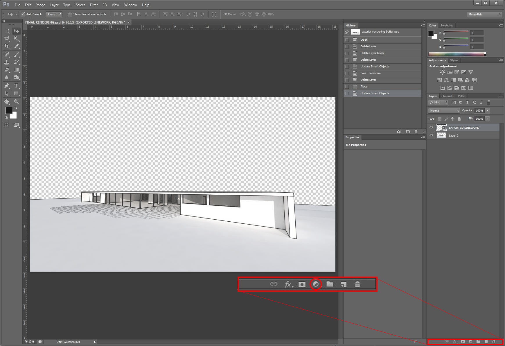
Since the purpose of this rendering is to render only shadow with an overlay of linework, it would be to the benefit of the goal of the final rendering to remove any distracting color cast from light sources that weren't corrected using white balance in V-Ray camera options. In order to do so, adjustments layers can be used. Selecting the fill and adjustments layer menu dropdown in the bottom right-hand corner of Photoshop (half black, half white circle).
Select Black and White from the options listed, and make sure that the black and white layer is above the rendered image in the Photoshop layers panel. Photoshop layers work hierarchically, and the adjustment layer will only effect layers that are below them.
Solid Background
Since the file-type the rendering was saved as was a .png, the background of the rendering was rendered transparent (no material). In order to create a background giving a neutral white sky to the now black and white image, adjustment layers dropdown can also create fill layers which are layers that are composed of solid colors.
Return to the fill and adjustments dropdown menu in the bottom right-hand corner of the Photoshop window, this time selecting solid color . When prompted to choose a color, either move the slider to the uppermost left corner, or enter the RGB/CMYK values for white.
Once the solid fill layer color has been specified, click okay . The layer may have been created over other layers, hiding their information from view. In order to make the solid fill the background color, click on the layer and drag it to the bottom of the layers in the layers panel.
Save as .PSD
To preserve the Photoshop editing capabilities, as well as the capability to edit the placed linework as vector smart object, save your rendering as a Photoshop Document (.psd) file. Do not wait until the end of the process to save, but rather save as you go. Once you are finished, you can save as a .jpg.
