|
Preparing Files for a Site Model: Laminating |
|
|---|---|
| Screenshot | |
| Using a digital model to prepare cut files for a physical site model using the LAMINATION method. Involves the Contour command and using all 4 viewports to Move section curves before using Make2D . | |
| Uses Tool(s) | Rhinoceros |
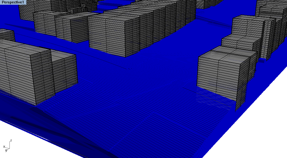
For this workflow, we will use vertical lamination for the buildings (think books sitting on a shelf) and horizontal lamination for the ground surface (think of pages in a notebook). The physical model will be made out of 1/2" wood and will be at 1/8" = 1'-0" scale . We will focus on the east edge of the site (in top view, the right side of the block). We will prepare cut files for the 13 buildings in this half of the block, as well as an isolated portion of the ground surface (including the street, sidewalk, and backyards).
Preparation
Before starting to prepare cut files, there are several steps to take.
Scale the Model
Use Save As to save the Rhino file as a separate file. This file will be used only for the preparation of files for physical modeling. Then, make sure no layers are locked and that no objects are hidden. Use the SelAll command to select all objects, and scale it to 1/8" = 1'-0".
Ground Surface
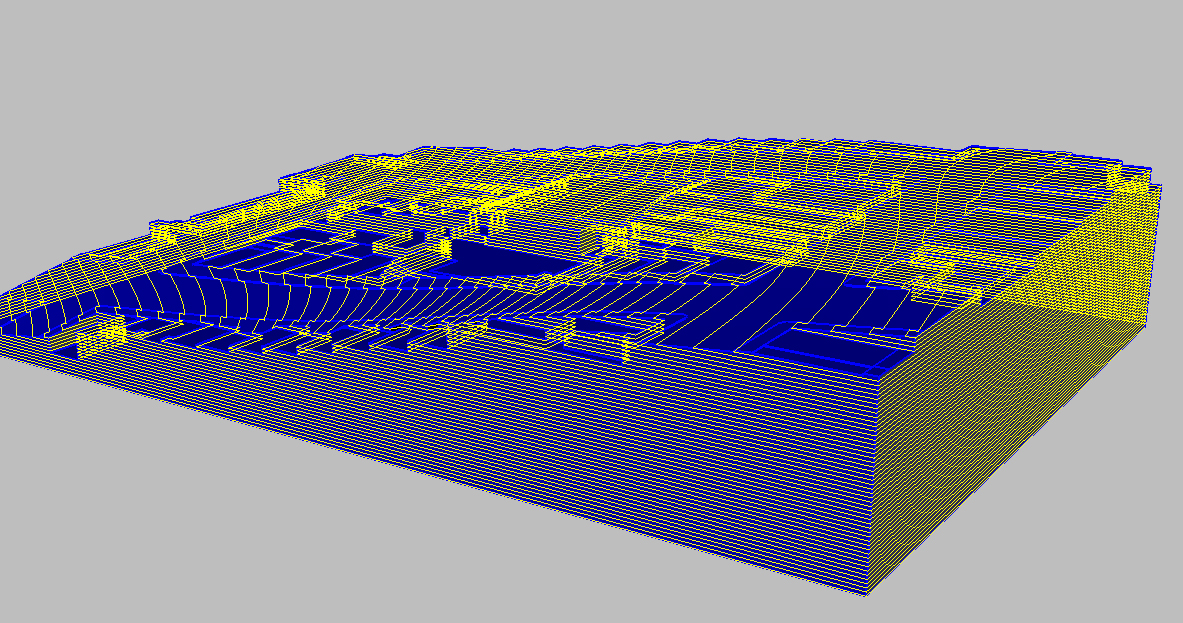
The ground surface has already been prepared for you using this workflow . The ground surface is now a closed polysurface (instead of a floating plane) and is ready to model.
Contouring the Ground
Now that the ground surface has been boxed out to form a closed polysurface, it is time to contour it. As mentioned above, the ground surface will be built from horizontal lamination (layers stacking on top of each other). This means that we must take horizontal contours through the object. Create a new layer called "Ground Contours" and make it the current layer.
Material Thickness
Before contouring the object, consider the thickness of the material that will be used to build the physical model. In this case, we are using chipboard that is exactly 1/2" thick, which means our contours will also be 1/2" apart.
Contour Command
Select the ground, type Contour and click the lower left corner of the object as the base point. Click the upper left corner of the ground surface next; this specifies that the contours will be perpendicular to the vertical plane, which means that they will be horizontal . Type 1/2" for the Distance Between Contours option.
Moving Contour Lines
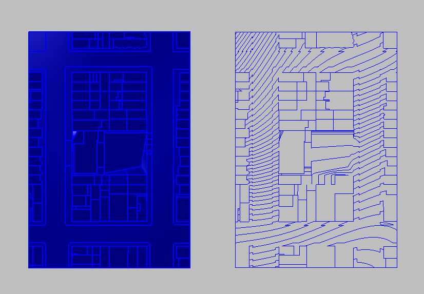
Now that we have produced the contour lines for the ground, turn off all of the other layers. Use all 4 viewports to move the contour lines so that they do not overlap or sit on top of each other. In front or right view, select all of the lines except the bottom line. In top view, Move these lines to the side so they no longer overlap. In front view again, Control+Click on the new bottom line to deselect it. In top view again, move the rest of the selected lines to the side. Repeat until all of the contour lines are sitting in a row in top view.
Make2D
Although in top view the contour lines appear to be cleanly sitting in a row, the front view shows us that they all exist in different vertical planes. To address this problem, select all of the lines and use the Make2D command in top view. Now the linework is all aligned in the same vertical plane and is ready to be cut. You can delete the old linework now.
Contouring the Buildings
For the buildings, we will repeat a similar process, this time using vertical lamination. It's easiest to do one building at a time.
Orientation
When using vertical lamination, there are still 2 options for which way the lamination will be oriented. The individual layers could be oriented north/south, or east/west. In this case, we want all of the buildings to be contoured across the short section of the site (east/west). Keep this in mind when contouring each individual building. This factor is determined by the second click of the contour command, where you specify the direction that is perpendicular to the contours.
Contour Command
Select the building, type Contour , and select the lower corner of the building as the base point. Select another lower corner of the building (keeping in mind the desired orientation), and type 1/2" as the distance between contours. Repeat the same process of moving the contours using all 4 viewports. Again, in top view use Make2D to flatten all of the linework to the same vertical plane. Move the lines for each building so that they line up below the ground surface contours.
Labels
Use the Text tool to label each row to keep track of the pieces. Place the labels on a separate layer called "Text" so that they can be turned off later if needed.
Submissions
Save the final result as a Rhino file (.3dm) and upload to your bSpace dropbox by the end of section.


