|
Modeling Site Information |
|
|---|---|
| Screenshot | |
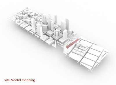
| This workflow describes the steps necessary to develop a 3d model and drawing of the site. Students will learn how to export and import data from/into rhino, scale to accurately reflect site data, model land and building information to create a precise site model | |
| Uses Tool(s) | Rhinoceros |
Creating digital site models can be a great tool for both creating site drawings such as plans and sections, diagrams, rendering context, as well as producing physical site models.
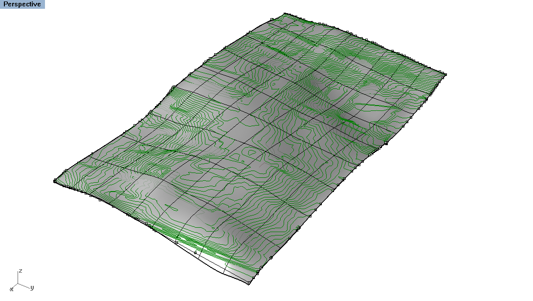
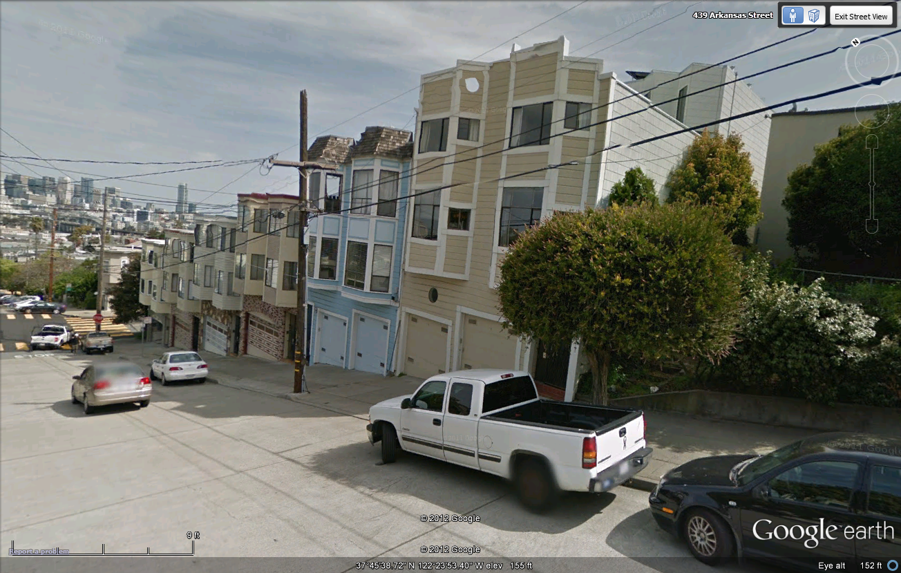
Sometimes you can download site information as mesh models, like the image below, however mesh models could be transferred to NURBS in order to provide linework. The steps below will outline how to create NURBS geometry from existing GIS information of the site and surrounding context and gather group data to produce a complete site model.
Steps
Rhino files associated with various steps are available to download. Simply click on the link to download the file and practice the specific step outlined below it.
Import + Organize
Step 1 - Rhino File
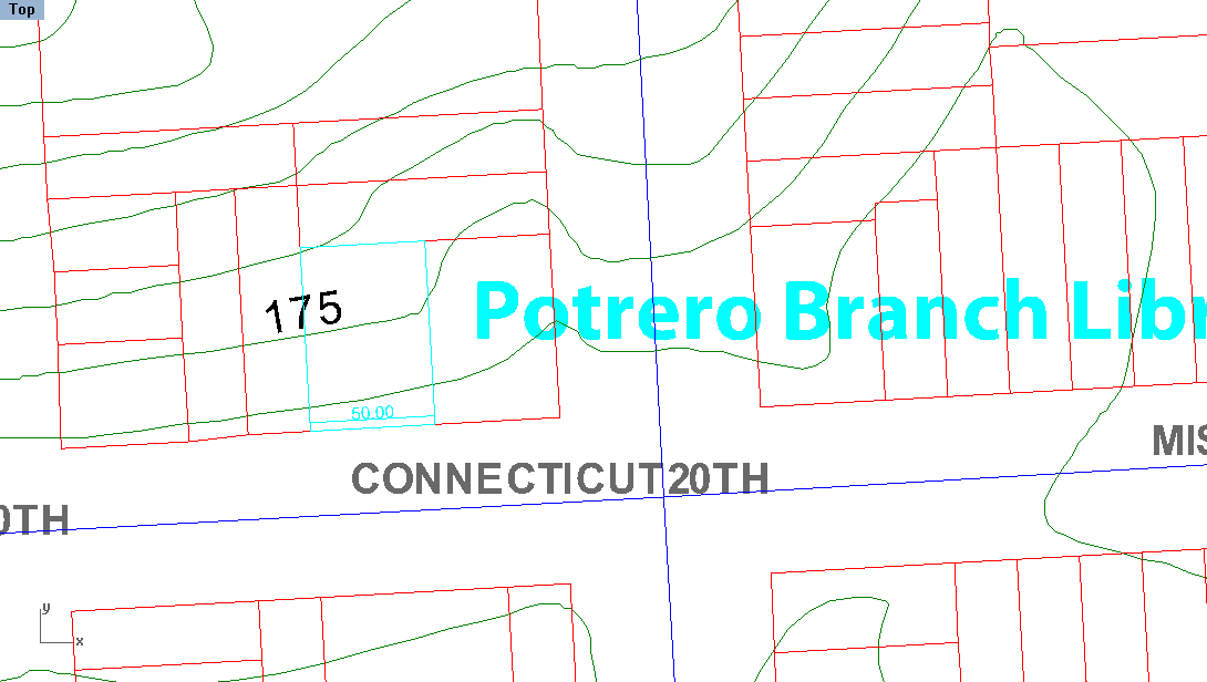
 Depending on where you received your information, it's important to organize it as much as possible prior to scaling and modeling. Whether the file is coming directly from GIS or Autocad, make sure that there are layers describing the following items which we will be modeling in this workflow:
- Streets
- Contours
- Building outlines
You may need to Explode data or Ungroup them in order to make them full accessible.
Scale
Before moving on - be sure to check the scale of your data! When transfering between programs, it is easy for data to be scaled improperly. Go to Options to make sure you are in Feet .
First, find a location where you know an established distance - like the width of a street or building lot. Use the Distance command to check what this distance is in the digital drawing. If the distance is off, select ALL of the linework (make sure all layers are unlocked) and Scale the drawing according to that distance.
=Create Topological Surface
Step 3 - Create Surface
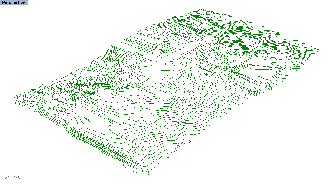 Raise the contour lines and use the
Patch
command to drape a surface over the contours. For more information on this process, follow this
workflow
that covers the details of creating a topological surface.
Project Linework to New Topo Surface
Step 5 - Project Curves
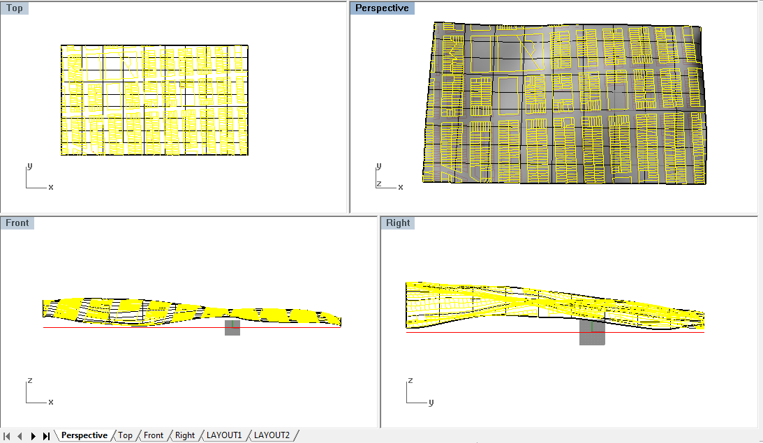 Now that we have the ground surface modeled,
Project
to project the curves onto the surface. Select the building outlines and roads as the curves you want to project and then in the
TOP
view, select the new topo surface as the surface to project onto. New linework will be created on the ground surface. Move this new linework to a new layer labeled "Ground Surface Linework".
Create City Blocks
 To create differentiation between the roads and the city blocks, we need to model the outline of each city block.
Copy
the ground surface and the city blocks outlines (that were projected) to the side in the
TOP
view. Use the city blocks to
Trim
the ground surface. You may need to
Extend
some of the lines to make sure they extend past the surface for easy trimming.
 Once you have the blocks trimmed, move them back to the original ground surface location. To give the blocks a height differentiation,
OffsetSrf
each block surface by 1/2 foot. Be sure to keep the options set as
solid'
so that it remains as one solid polysurface.
Extrude Buildings
The next step is the most tedious as it involves gather more information that what we have in the drawing: building heights. Focusing on one block at a time, find the same location in Google Maps. Enter to street view to look at the building's elevation.
For each building, to calculate the height, count the number of stories from the lowest point on the ground (if on a sloped site) and multiply by 12 feet. If 3d buildings are modeled in Google, you can also attempt to calculate the heights from these buildings.
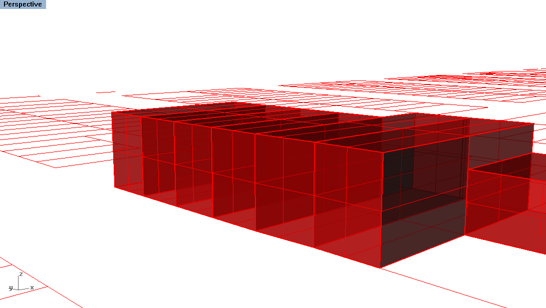
Return to the original building outlines (located on the c-plane, not the ones projected) and Extrude the
Move Buildings to Site
Once the buildings are extruded, you then need to move them up to the right location on the ground surface. Especially on a very hilly site such as Potrero hill, this is where you will start to notice the building heights sloping just like the site itself (despite the fact that we generalized all stories to be 12 feet).
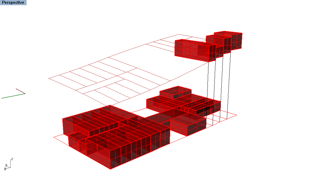
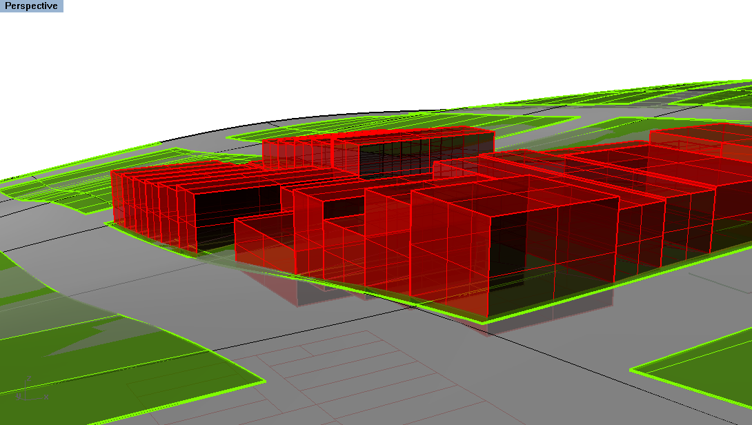
It is important to keep the OSnaps on the right setting when moving the buildings up. For each building, Move the building from the corner where you measured the story height. This should be along the road you were viewing the building elevation in Google Maps. Select the building and Move it by selecting the front corner and moving it vertically to the same corner that was projected on the ground surface.
Note: Depending on the topographical conditions of the site, not all four corners of the building may touch the ground. In this case, use the Scale1d command to extend the building way down past the ground surface for easy trimming. Then use the Trim command to trim the building at the ground.
Combining Data with others
To make a large site model in a much faster manner, you can easily divide the city blocks with other collegues to divide and conquer the modeling tasks. To do this, use the ExportSelected command to export different city blocks. Or share the same original file with all the ground surfaces created (all the steps previous to Extruding the building).
Then each student should take a city block to measure the building heights and extrude. To combine the file, simply open the Master file and each student file in two different Rhino windows. Use the CopyToClipboard command to copy the work into the Master file. If the work all originated from the same Master file, the buildings should be copied into the same located of each city block (and the same layer name, if using the same layers). This is because Rhino is based off a coordinate system - that was set up and organized in the same Master file was distributed.
Common Problems
- When we join our rhino files together, they don't match up at all. What did I wrong?
- You did not divvy up the model well.
Additional Resources
- Modeling Topographic Surfaces
- Using site contours, this workflow show how to use the Patch command to create a surface represented the topography of the site.
- Basic Rhino Commands including Patch
- This YouTube reviews the same tools as the workflow above but in one long video format. From Nick Senske's UNC course on digital representation.
