|
Drawing site sections from a digital model |
|
|---|---|
| Screenshot | |
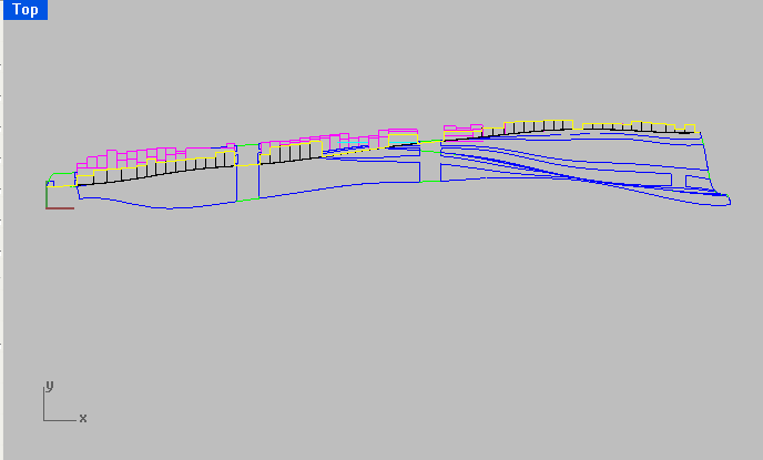
| Using a digital site model it's easy to extract information to make site plans and sections. This workflow reviews the process of making a site section by cutting, Make2D and editing line work and exporting to Illustrator to produce a final drawing. Conventions specific to site drawings will be reviewed. | |
| Uses Tool(s) | Rhinoceros , Illustrator CS5 |
Steps
Clean up model
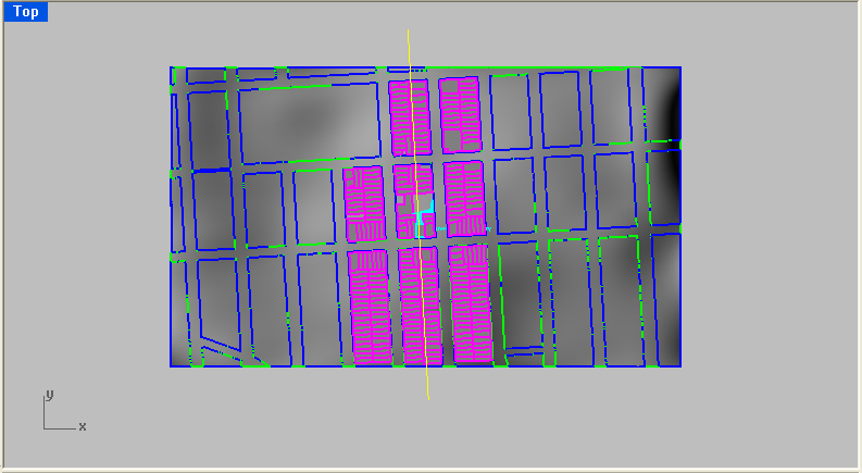
Delete all line work to start with a clean digital model of just the site, sidewalk and ground surface and surrounding buildings. The more detailed the original digital model, the more detailed your line drawing will be. To do this, use the command SelCrv to select all line work and delete it.
Make cut plane
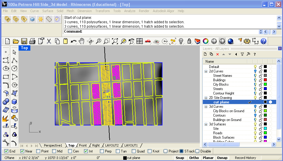
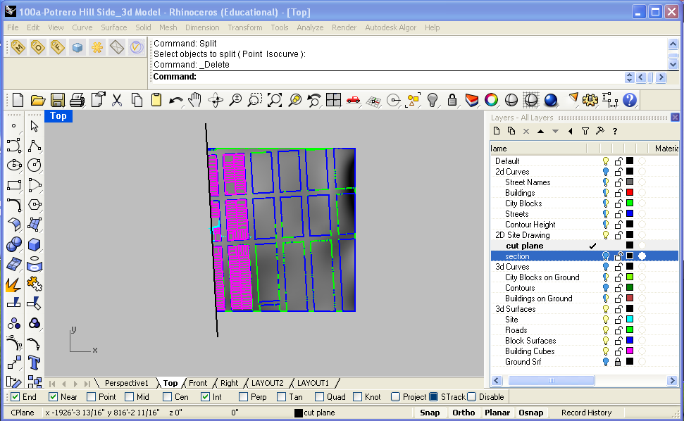
In Top View, draw a line perpendicular to the site to define where you want to take your section cut.
Using this line as your guide, use the command CutPlane to create a cut plane that you will use to make your section cut. Make sure to select everything so the cut plane extends beyond the site to include surrounding buildings.
Section
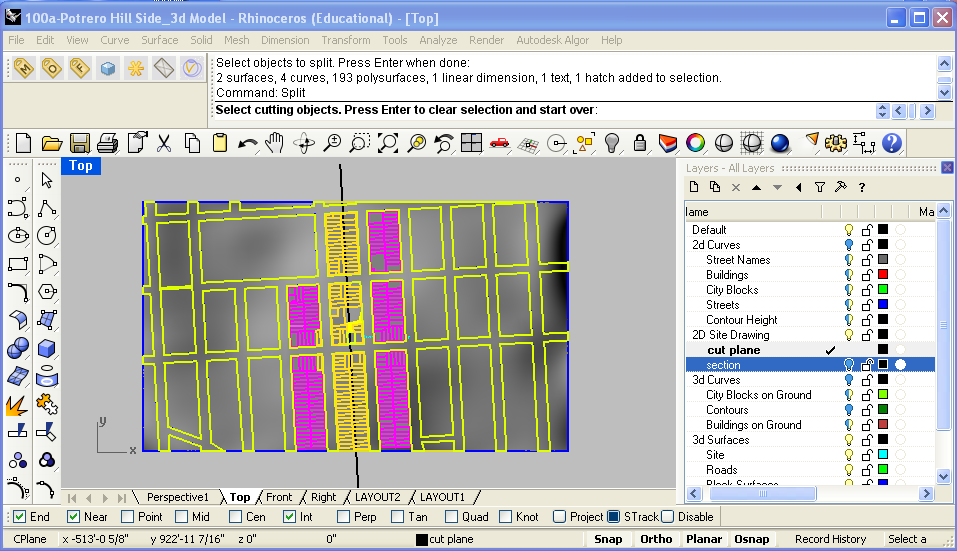
In a new layer, use the section command to create a section through the digital model along the cut plane you created.
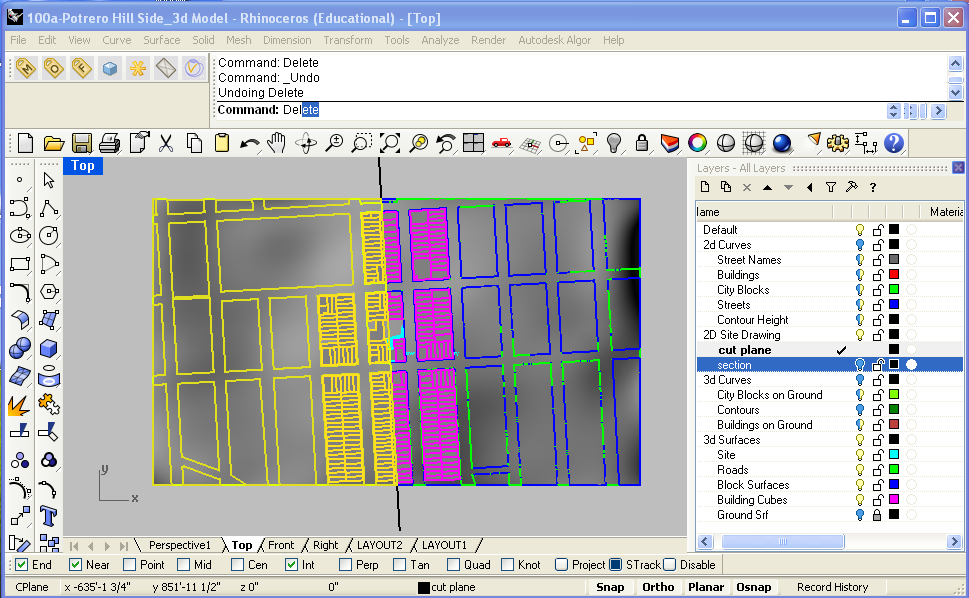
After creating the section line work, use the cut plane to Split and Delete half of the model.
Rotate Sectioned Model
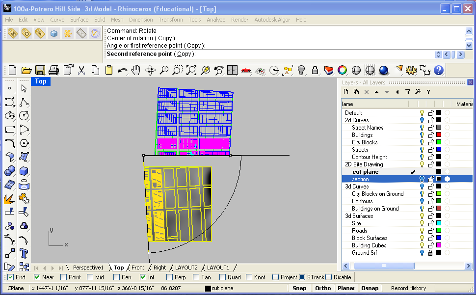
In your top view, select all of the objects and curves and rotate them so that they are parallel with the x axis. This way, we can still use the Front view to produce all of the line work with the Make2D command.
Make2D and edit line work
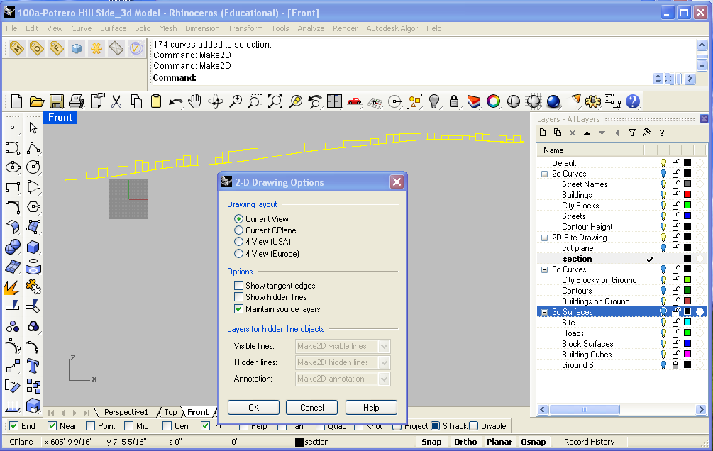
Hide all of the layers except for the Section layer that you produced in step 2 - this should be your section line work. In Front view, select this and use the command Make2D .
Clean up this line work so all corners are precise. Under the Section layer, use the Polyline command to retrace the overall outline of the buildings and the site combined and then delete original Make2D linework. The final outline should look like the example below. Be sure to Join or Close the curve when finished.
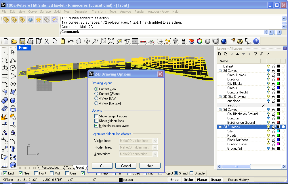
Return to Front view to Make2D the rest of the digital model to produce the background linework (everything behind the section cut). This should include all of the remaining surfaces in your model.
Line up the Make2D output with the Section cut so that they match up.
Hide the Section layer and work on organizing line work into new layers (such as medium, thin, thinnest lines).
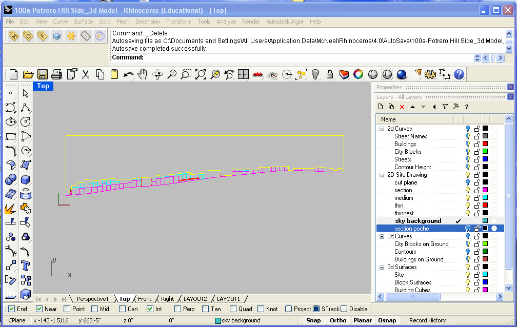
To create the sky outline, turn on and lock all of the layers for the section and the background. Create a new layer called "sky outline" and retrace the top of the building profiles and create a closed curve by extending the edge of the drawing up (where the sky is located behind the buildings) like the example below:
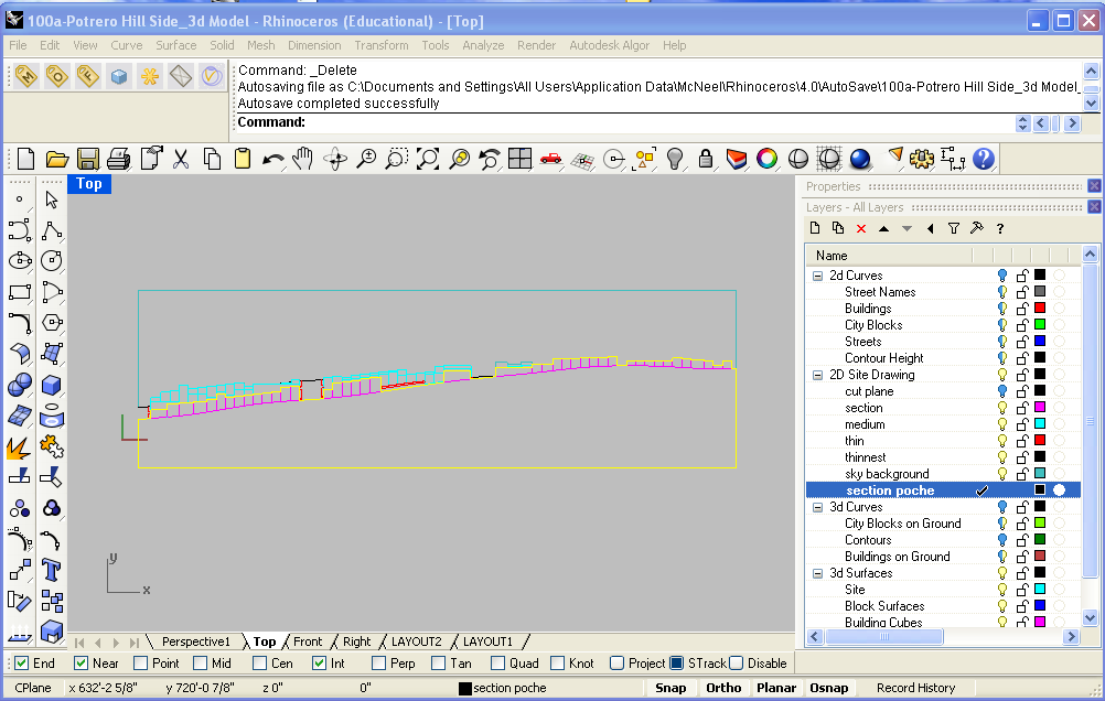
Create a new layer called "section poche" for the section fill.
Both of these poches should be closed curves so they will be filled properly when brought into Illustrator.
Export to Illustrator
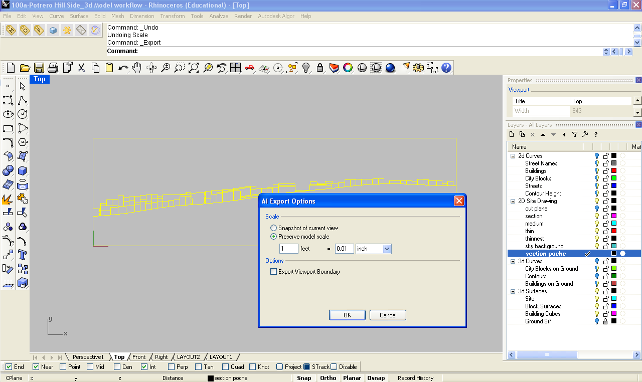
Select all of the line work and export selected as an illustrator file with the scale preserved.
NOTE: figure out what scale will fit on an 11x17 and include here
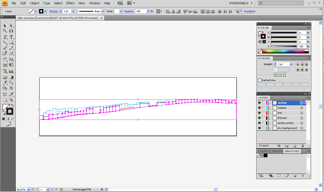
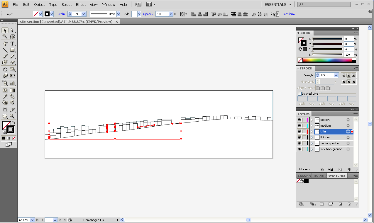
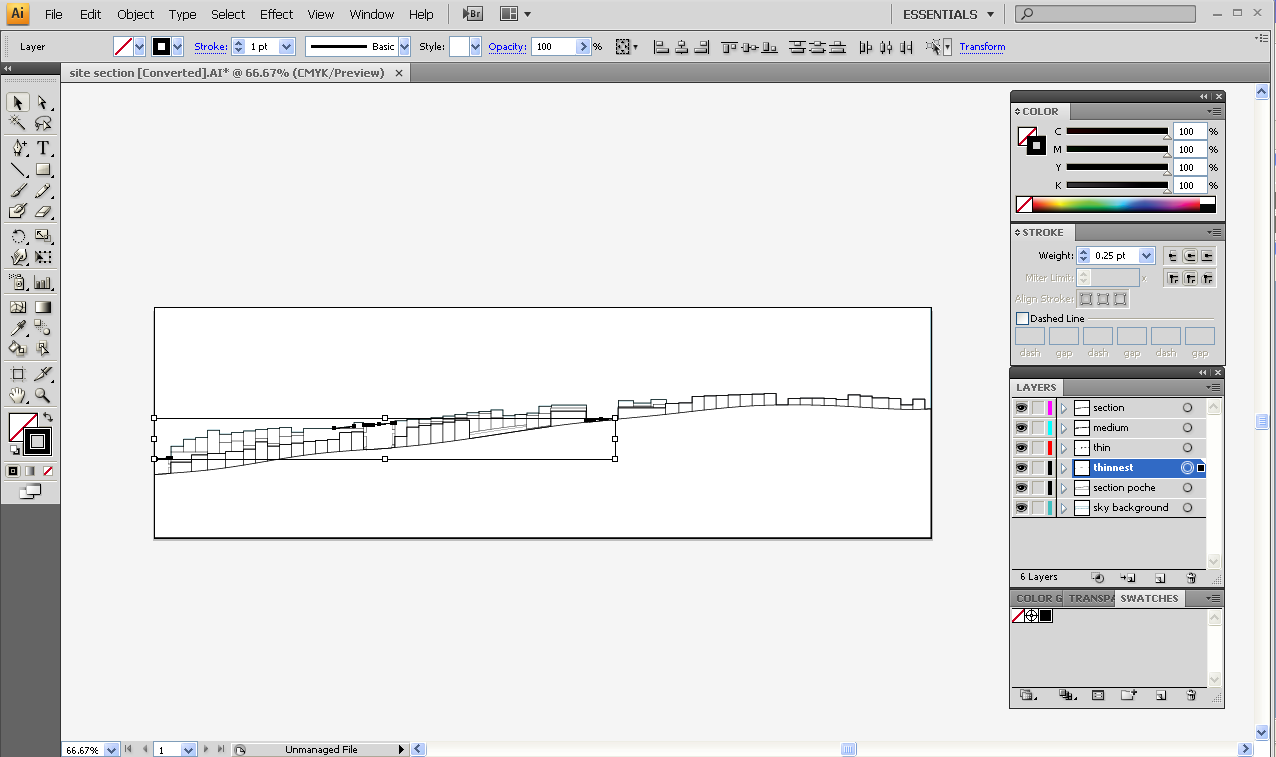
In Illustrator, change the line weights and add a fill to the section layer. Make sure that the section layer is the top most layer so that all other line work is behind it.
Change section cut line weight to 1pt
Change medium line weight to .75 pt
Change thin line weight to .5 pt
Change thinnest line weight to .25 pt
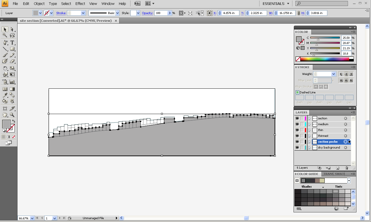
Add a fill to the "section poche" layer. Make sure the stroke does not have a color selected:
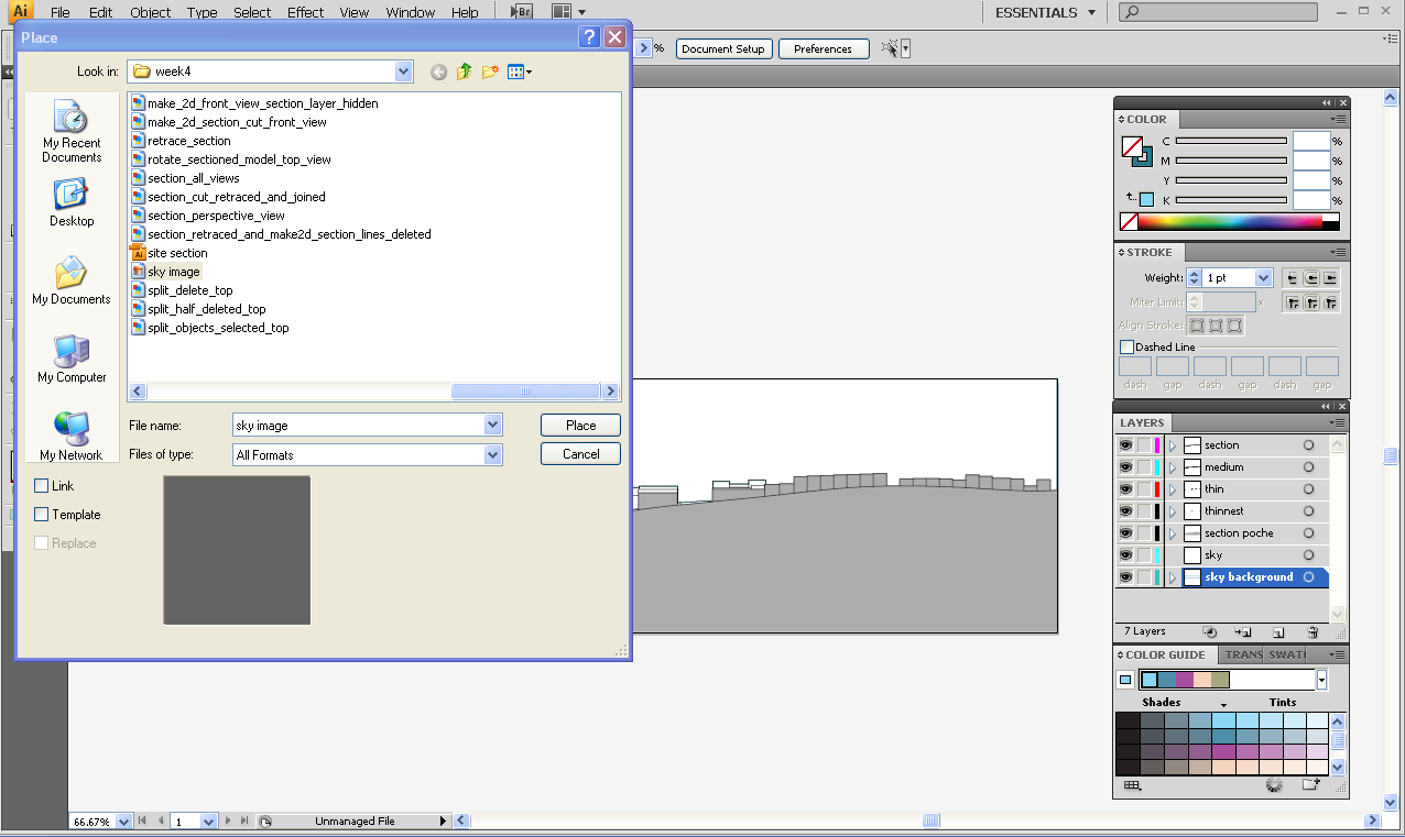
To add a sky background. Google search for a sky image and save it. Create a new layer called "sky" then go to File -- Place and select the image to bring it into Illustrator.
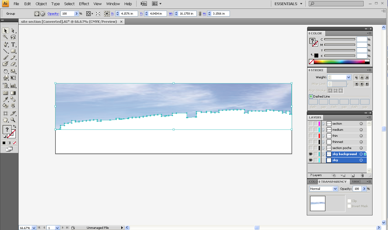
You can use the clipping mask command to remove the portion of the sky image that falls behind the profile of the buildings in your site section drawing. To do this, select the "sky background" layer you created in Rhino and the sky image you just placed in Illustrator. Then go to Object -- Clipping Mask -- Make, to make the sky background fit behind the profile of your site section drawing:
Turn back on your other layers, add text (be sure to note scale 1' = 1/100").
Add a background image and entourage
Go into google image and search for car silhouette. Save or copy the image into Illustrator (be sure to copy it onto a different layer). Select the object and use the Live Trace command and make and expand.
Common Problems
- When opening the drawing in Illustrator, it says that the file is too large for the artboard and I cannot move it.
- This is probably because you did not scale the drawing properly when exporting it from Rhino. Either re-export the file from Rhino, and be sure to use a decimal as the scaling factor, or open the Transform tab in Illustrator to re-scale the image.
Additional Resources
- Digital Fundamentals - Site Sections
- This long video overviews many of the same elements discussed in this workflow as part of UNC's digital course on representation. Earthy elements such as streams and roads are emphasized here when creating the final site drawing.

