|
Create a Custom Perspectival Underlay in Rhino |
|
|---|---|
| Screenshot | |
| Demonstrates the creation of a custom persectival underlay aligned with a 3d view in Rhino | |
| Uses Tool(s) | Rhinoceros , Illustrator CS5 |
Steps
Create a 3D grid / wire frame
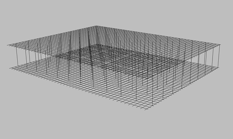
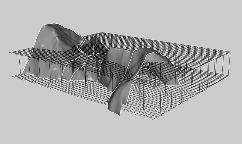
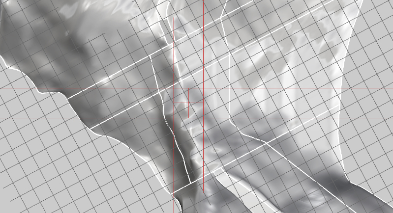
Create a simple grid that is about the size of the project (l, w, h). Then take the outside lines and extend them. These will serve to show objects in the distance at an appropriate scale. We can make a grid that is oriented to the site (North South East West), and another grid that is oriented according to other considerations. Put them on different layers for more control. The site grid can be made with a scale that is appropriate to the site - in the case below the grid is on 20' x 20' modules. Once we've made it we can copy it up and then draw vertical grid lines - these do not need to be so fine - perhaps a multiple of four or so. We will later move the grids in the Z-direction base on the camera view we create.
And a second grid that is for the architectural intervention or some other consideration.
Create a camera view in Rhino
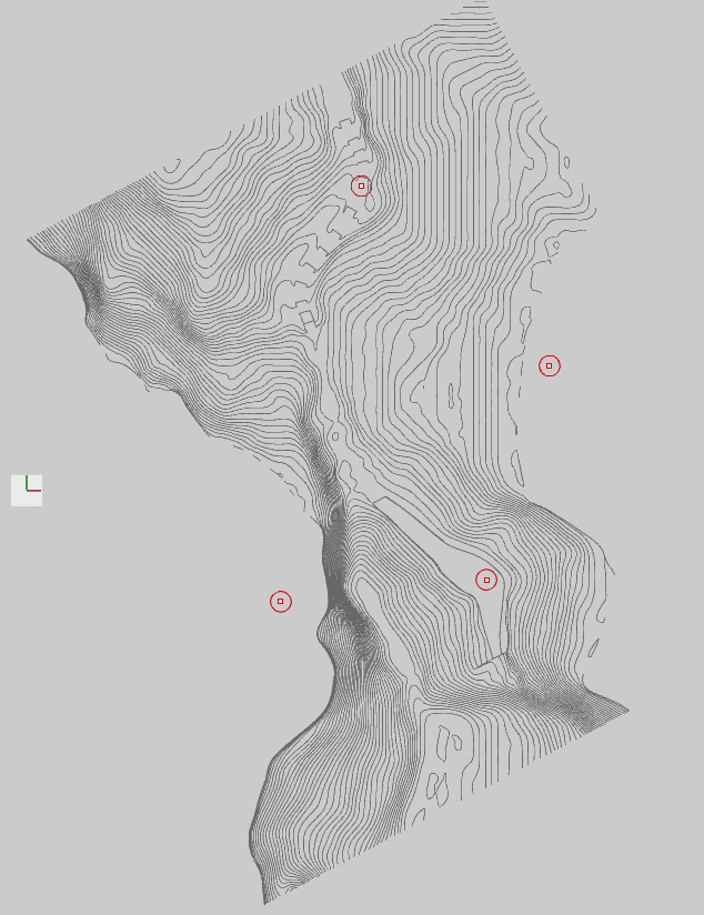
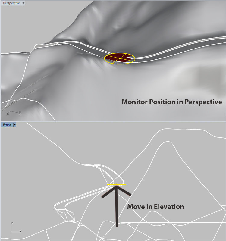
After we think about the views we want to create, we can place points on the plan where we want the camera to be and another point where we want to look. Place these points in Top view and then move them into place in Right, Front, or Left view. Use the perspective view to monitor where the point is in space. It may be helpful to create a larger circle around the point and move it with the site surface on. This way it will be more obvious when the point is above the ground, on the ground or under it.
By setting a camera position and target, we can better control the view. A two-point perspective would be one that has the camera and target at the same height.
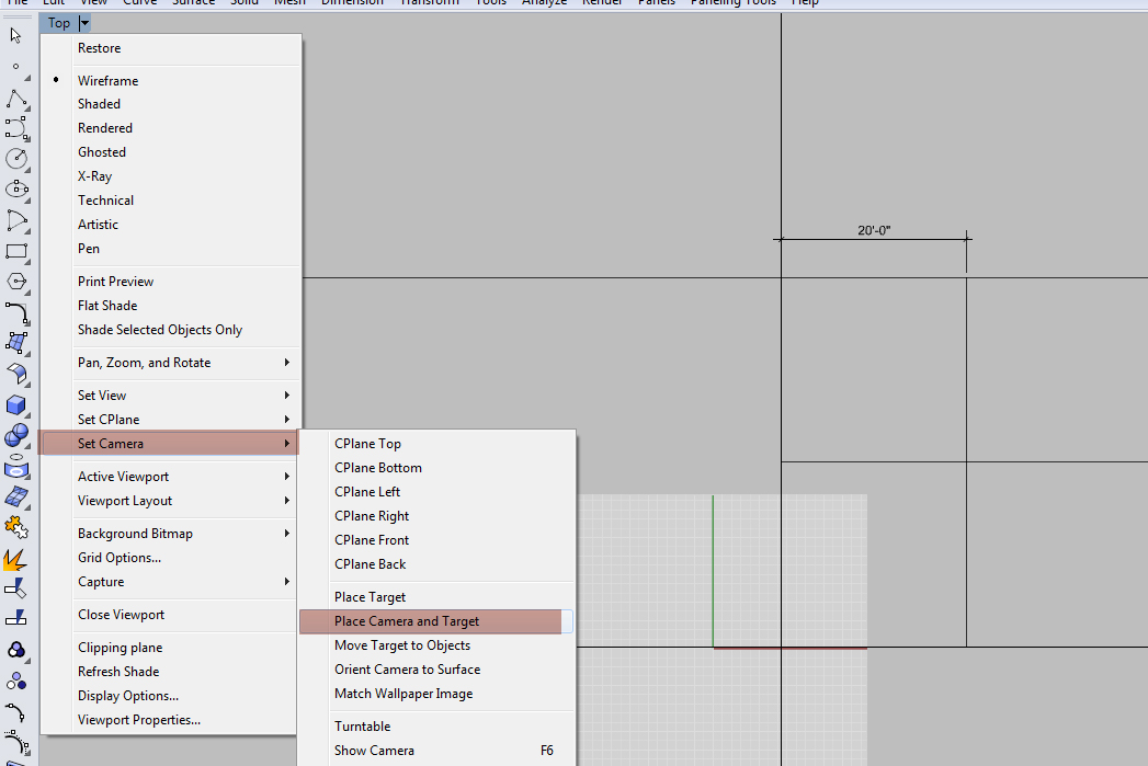
Go to: Set Camera/Place Camera and Target
In Top view, click to the position point and then the target point. The view will change to show what the camera sees.
In Viewport Properties, set the view to Perspective and set the lens length to 35 mm (a wide lense good for exterior views that does not noticeably distort geometry). Make sure the camera position and target position are at 65 (if the drawing units are set to inches - as they should be for architectural projects - then these numbers are inches). 65 inches is the average human eye level. If working on a camera level that is at elevation, add 65 inches to the camera position z-value and the target z-value. If the view is not working for your purposes, go to a 3-point perspective by adjusting the target z-value higher or lower.

With the new view activated, hit F6 to display the camera. If it is not sitting on the position point desired, move it to the point. It might also be necessary to move the target to the target point.
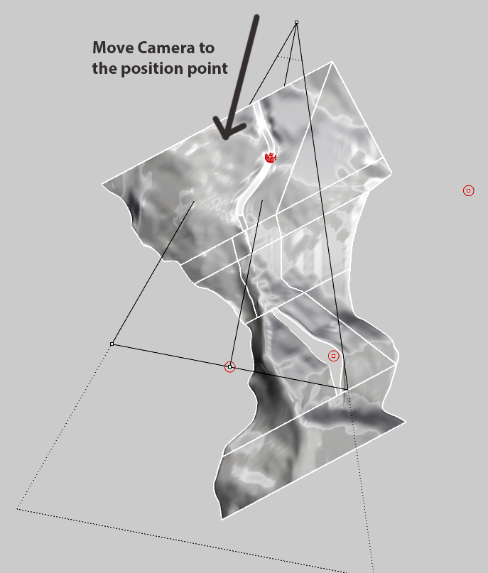
Once the camera is in position, and the view properties are set, we must name and save the new view.
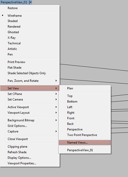
Print from Rhino
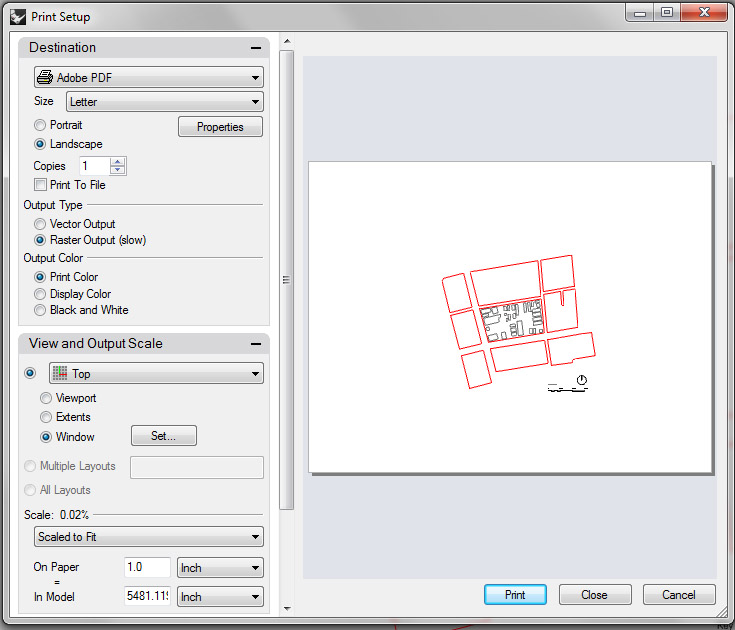
If we just need to get this underlay printed like a screenshot, we can print directly from Rhino. Ctrl+P brings up the print dialogue. Set the destination to Adobe PDF. Choose the media size and orientation. Then set a window about the geometry. Perspectives are not to scale, so choose Scale to Fit.
Export to Illustrator
Before we export the line work we need it to be two-dimensional. We can do this with the Make 2D command. Be sure to have the topo surface layer on and unlocked, and surface isocurves toggled to not show (in the surface properties dialogue). This will hide geometry that is beyond, and keep the linework cleaner and easier to read. Turn on the most appropriate orientation of site contours for the view. Be sure to have the camera view selected. Select all (Ctrl+A). Then type Make 2D in the command line. After running the command, look for the linework in the Top View. It will be small and near the origin. Now we can hide the 2D copy of the topo surface layer, leaving only the contour lines to show site topography.
Export to Illustrator
Select the 2D geometry and type Export into the command line.Perspectives have no architectural scale, so select to export the screen.
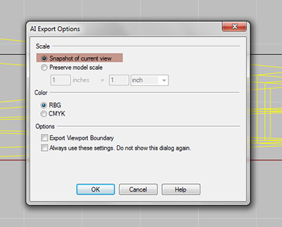
Alternatively, we could export the linework at 1:1 scale. It would be small in Illustrator but we could scale it up there.
Common Problems
"When I set the camera, the z-value is always zero."
- When selecting camera position and target points, make sure that Project is toggled off.
"I made 2D but nothing happened. I don't see the 2D linework anywhere."
- After Make 2D of a perspective view, the linework is at a very small scale near the origin. Zoom in to find it.

