|
Creating a 3D Rhino model from plans and elevations |
|
|---|---|
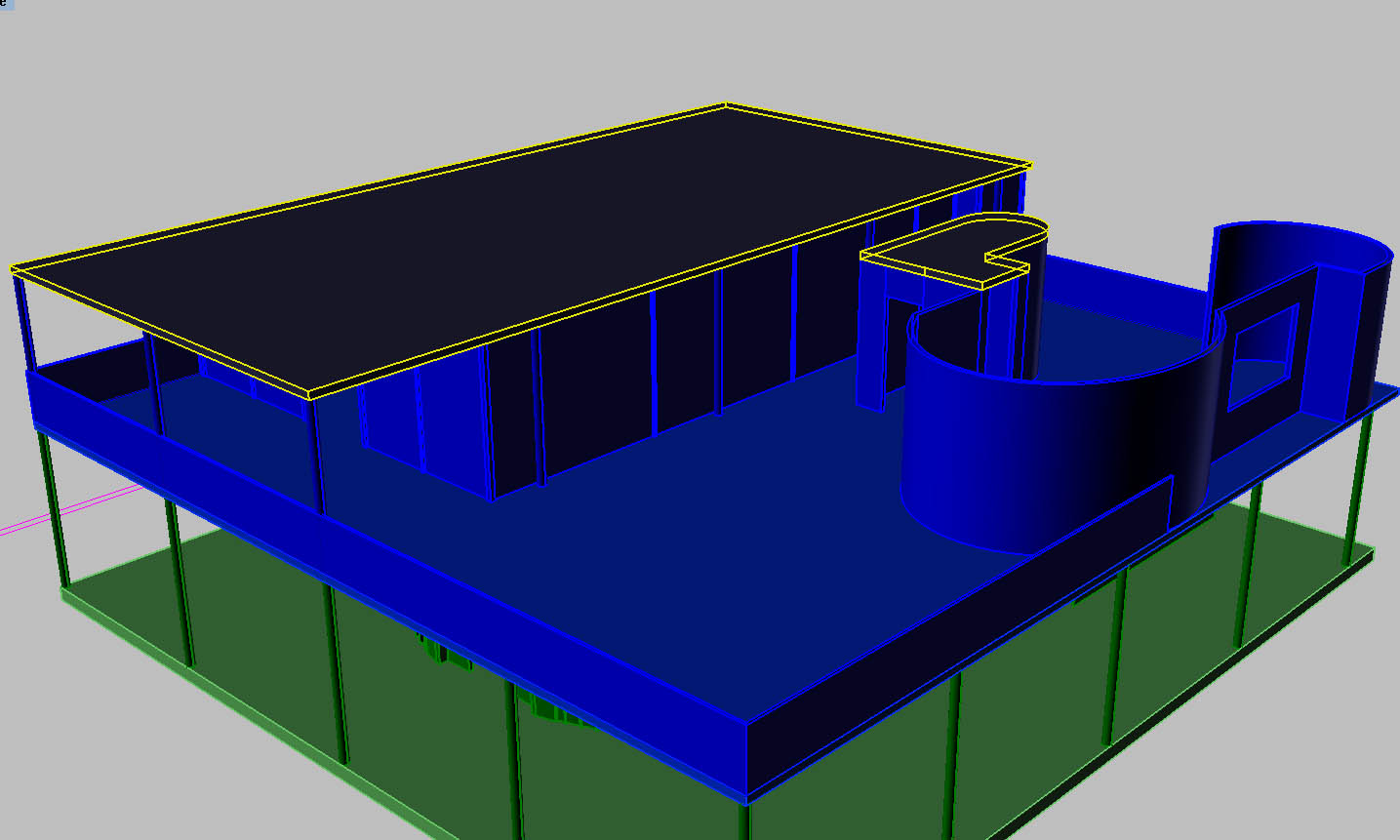
| Screenshot | |
| Introduction to 3d modeling in Rhino with specificity towards a building model. Modeling from Lines to Surfaces. How to keep a model "clean" and organized while also exact. Surface editing tools. | |
| Uses Tool(s) | Rhinoceros |
Download the 2D linework needed for this workflow here: Villa Sav-arnsworth House
Preparation
Take in general observations of the building
Our linework is taken from a hypothetical house consisting of Mies van der Rohe's Farnsworth House sitting atop Le Corbusier's Villa Savoye. Before diving in - take a look at the perspectives to get a general idea of what the final model will look like.
Settup 2d Linework
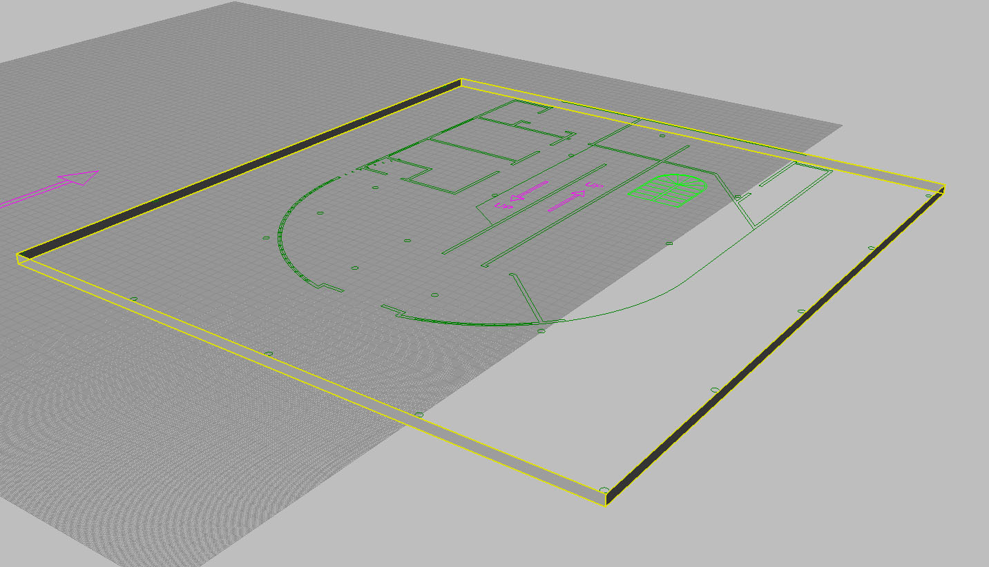
Stay organized and leave a copy of the original linework intact. Continually lock any unused layers to maker sure they are undisturbed. Make a copy of the plan linework and move it diagonally so you wont accidentally select the original linework in any of the viewports. Hide the original linework.
Raise Linework
Measure the distance between the top of the first floor to the top of the second floor in one of the elevations. This should measure 12.' Select all the linework of the 2nd floor (in the layers box - expand the "2nd floor plan" layer, highlight all the layers underneath, right click "select objects").
Hold down CTRL and de-select the original linework we are preserving. Raise the remaining linework 12 feet vertically. Make sure that the linework is raised perfectly vertically in an elevation viewport, using the ORTHO selection or holding shift down.
Do the same for the "2nd floor roof" layer. Measure the elevations to find the right height to raise.
Extrude First floor
Extrude Base Slab
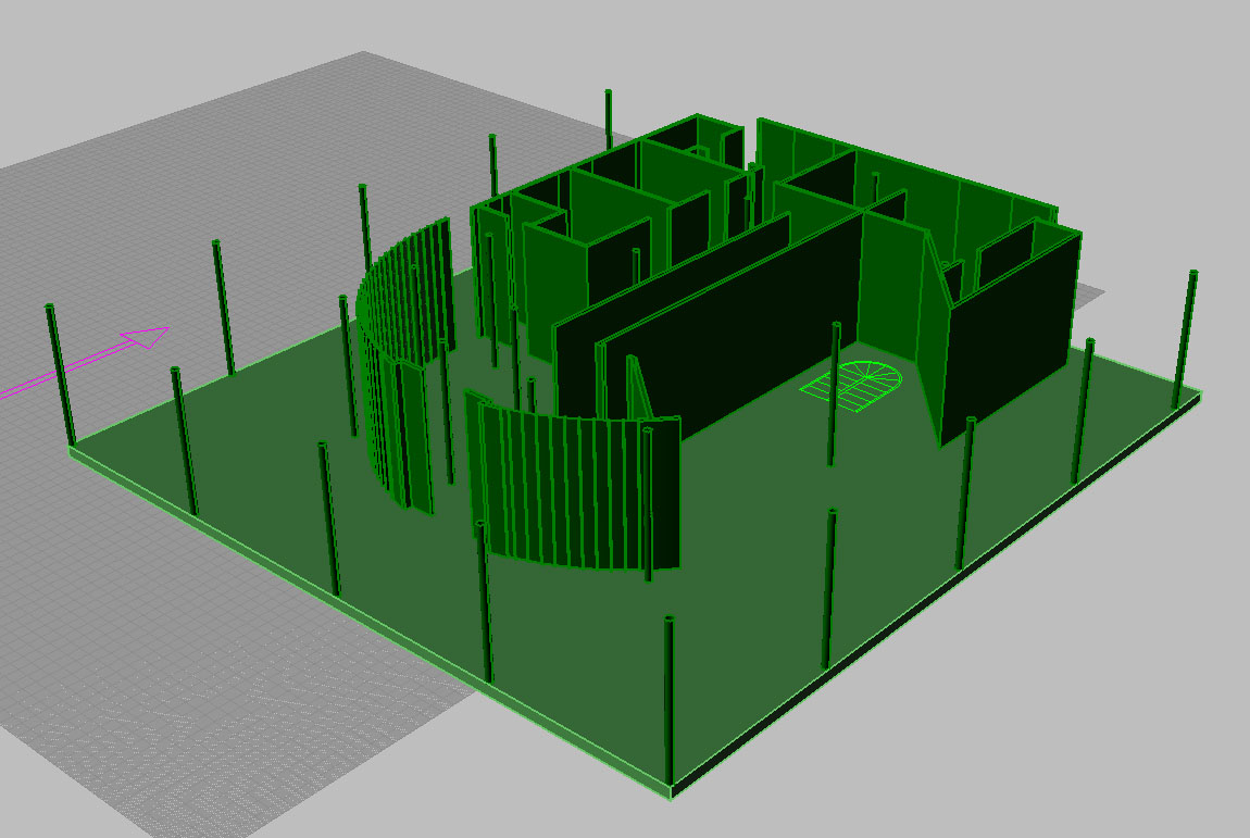
We will create the slab of the house by selecting the slab perimeter curve for the first floor plan and use the ExtrudeCrv . If we measure the elevation we see that the slab is 1' thick (do this with the distance command choosing tow points) . Enter -1' so that the slab extends below our plan. The direction of the extrusion should naturally happen on the Z axis (up and down) - if it doesnt you may have to specify the direction manually.
With the new polysurface selected, use the cap command to add a top and bottom.
Extrude First floor walls and supports
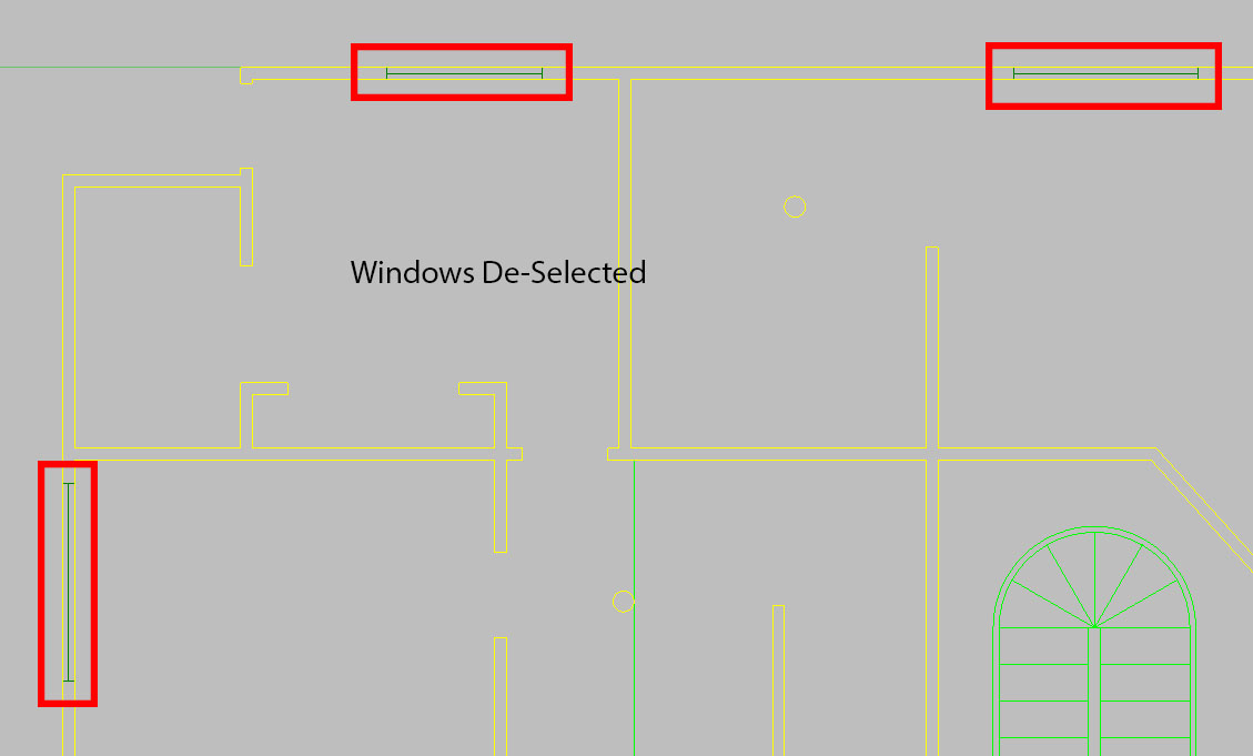
Right click on the "first floor plan" layer and "select objects." Make sure you de-select the linework for the windows - so that only the closed curves for the walls are selected. If you extrude the linework with the windows selected this will interfere with the Boolean2Objects command later.
Use the ExtrudeCrv to extrude the linework vertically 11.5.'
First floor Clean Up
Windows
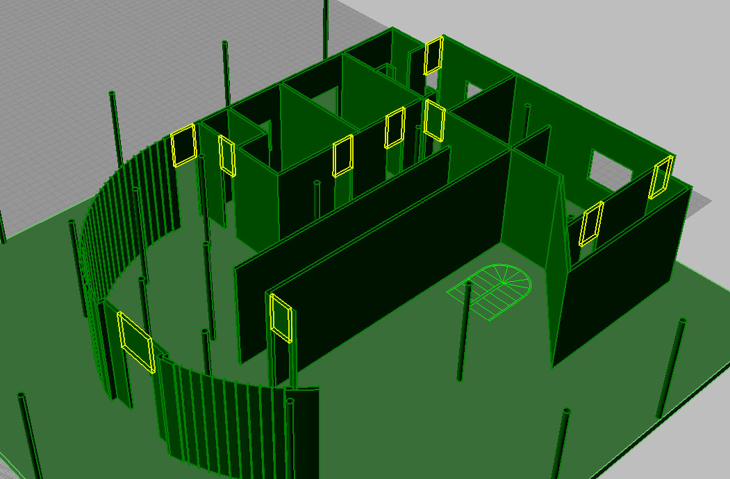
We will now cut the openings for the windows using the Boolean2Objects command.
We will need to reference the elevations to see how high off the ground and how tall the windows are. Then we will use the positions of the windows in the plan to create the boxes for the Boolean2Objects command. You may have to hide the walls to see the plan. Use the box command with the "3 point" option to make a box with the exact width of the guidelines and 4' tall. The width of the box does not matter - it just has to be thicker than the wall to make sure it can cut through. After making each box - move it towards the wall so that it protrudes out the other side.
Once the boxes are made, select them all and move them 4' vertically (in the appropriate viewport). Then use the Boolean2Objects to individually cut out the windows.
Blocking above doors
If we look at our 3D model we see that the doorways extend to the ceiling - but according to our elevation drawings the doorways are 8' tall. We must add boxes that are the width of the walls and 3.5' tall above the doorways to fill in these gaps. Do so with the Box command using the "3 point" option. There should be 10 blocks total.
Ramp
First we want to make the landing at the midway point on the ramps with the Box command using the "3 point" option - using the plans for the foot print and setting the height to 6'.
Use the Box with "3-point" option twice again to make the ramps. Take notice of the arrows in the plan to determine where the ramp begins and ends. The top of the first ramp should be flush with the top of the base slab and the top of the midway landing box. The top of the second ramp should be flush with the midway landing box and the level of the 2nd floor plans (12'). You will need to turn on the 2nd floor plans for this (keep it locked so it is not disturbed).
Spiral Staircase
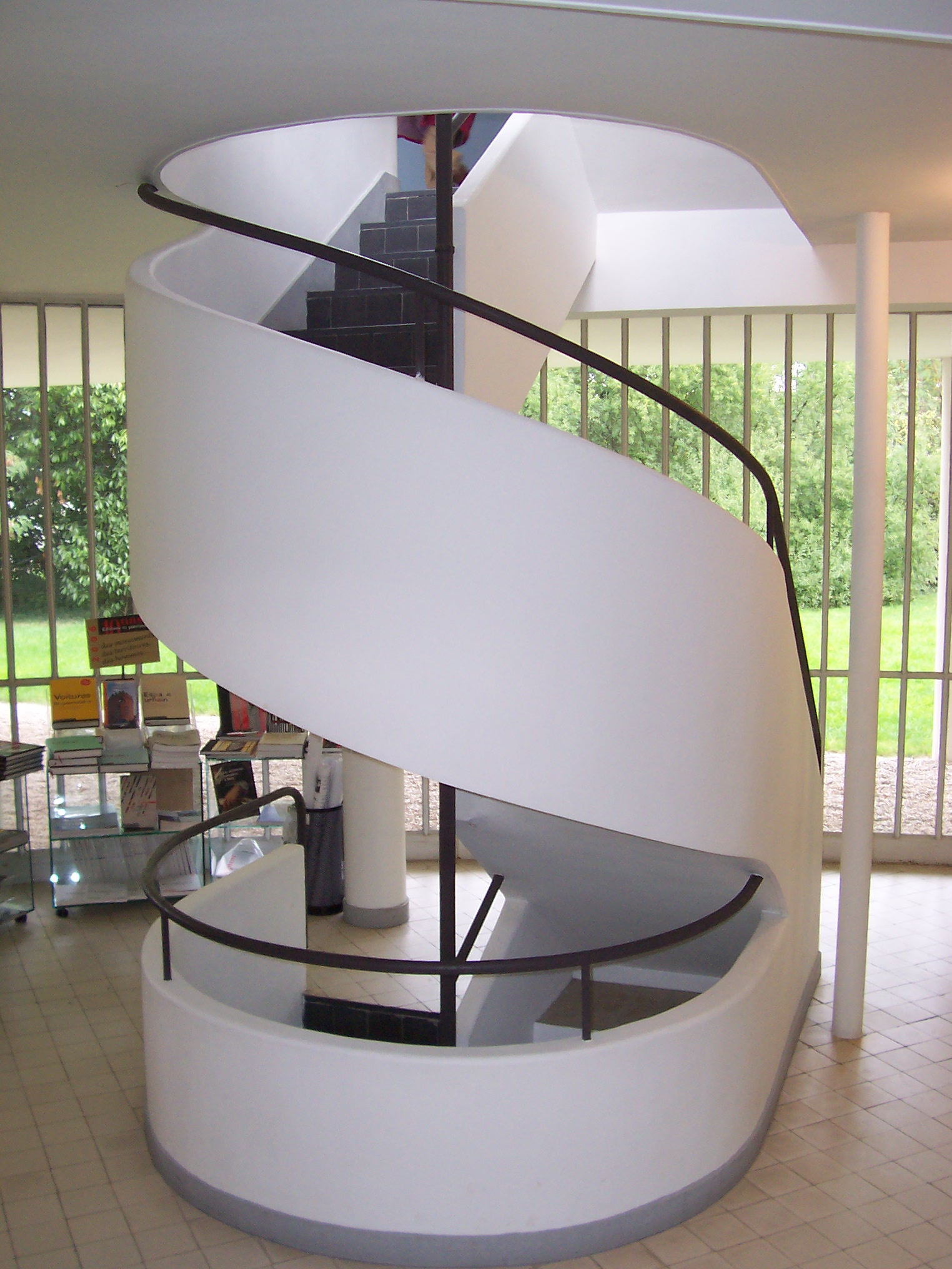
These are what the true Villa Savoye stairs look like.
Ours will be similar except with no railing, a solid wall in the center, and floating steps.
Create steps
Use the planarsrf command to create surfaces for each step and then extrudesrf to extrude the surface vertically 2."
Then move the steps vertically with each raising 9". You can begin by selecting all and moving them 9", then deselect one at a time and move the rest, using the center support wall as a guide to make sure we are moving the steps perfectly vertically. When finished check the top viewport to make sure the steps stayed in position and turn on the 2nd floor plan to make sure the top of the last step is flush with the 2nd floor plan.
Create Stair Railing
Next we will create the linework for the stair massing. This must be exact. 1. Begin by using the spiral command. Choose the bottom of the lowest pie-shaped stair for the "start of axis" and the top of the higher stair for the "End of axis."
2. Set the "Turns" to .5 and the "First radius and start point" to the outside-lower corner of the bottom pie shaped stair and the second radius to the outside - upper corner of the top stair.
3. Next draw two lines - from the lower end of the spiral curve to the bottom corner of the bottom step and from the top of the spiral curve to the top corner of the top step.
4. Offset these three lines 2." Make sure to offset in the "top" viewport. Draw connecting lines at both ends and at the junction between the spiral and the straight lines.
5. Use the EdgeSrf command to create three different planes.
6. Use the ExtrudeSrf command with the "both sides" option selected to extrude the surfaces 3.5' in either direction. Use the slab to trim the piece of stair railing extending below the first floor. Later we will use the second floor to trim the top railing.
Create Second Floor
Create second floor slab
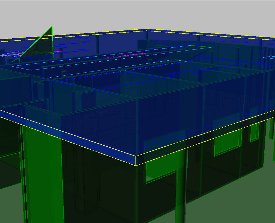
Select the linework of the "floor" sub-layer within the 2nd floor plan layer. Use the PlanarSrf command to make a plane, and then the ExtrudeSrf command to extrude the surface -.5' so that it extends 6" below the plan linework. It should touch the walls and supports of the first floor. Use this slab to trim the piece of stair railing extending from the first floor.
Cut openings in slab
Select the linework for the ramp and stairway opening. Use the ExtrudeCrv command with the "BothSides" option selected to extend them beyond the slab. Then Boolean2Objects each of the openings.
Extrude 2nd Floor
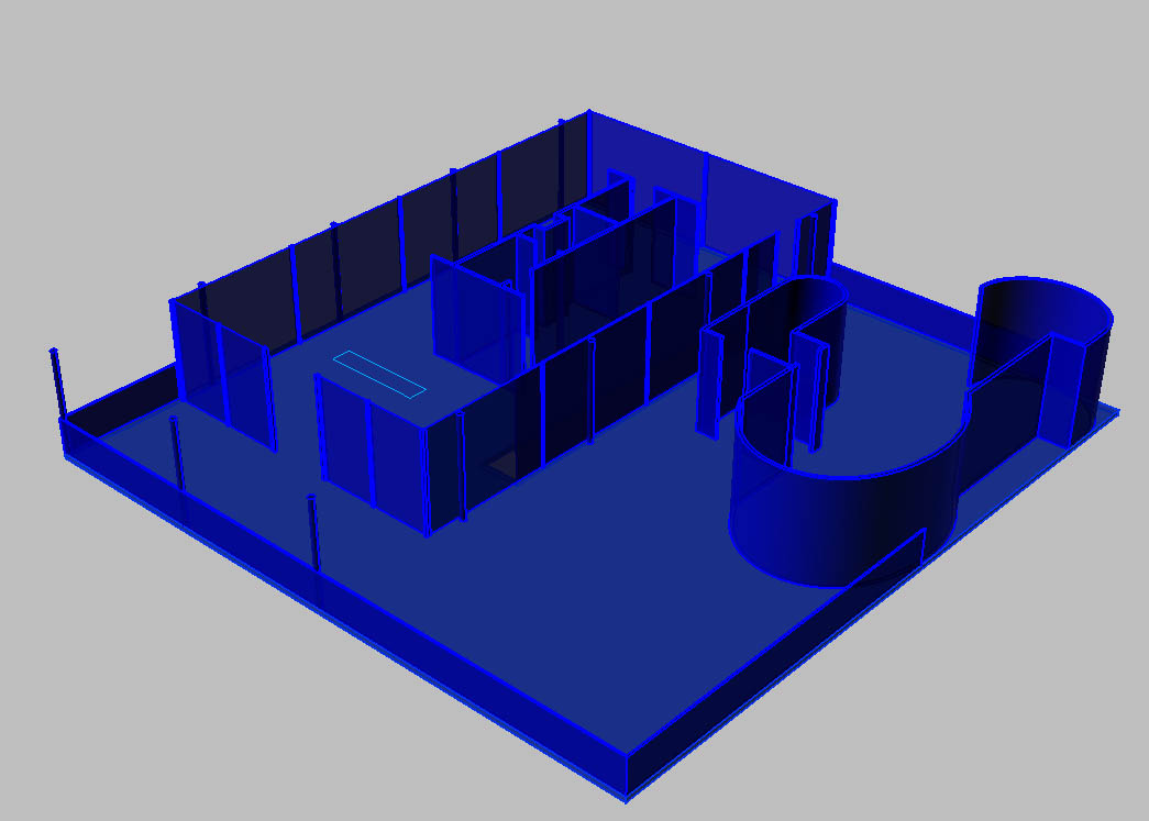
Right click the "2nd Floor Plan" and "select objects." ExtrudeCrv this linework vertically 10'. Do the same for the "railing" linework and extrude it 3.5.'
Cut window in roof solarium
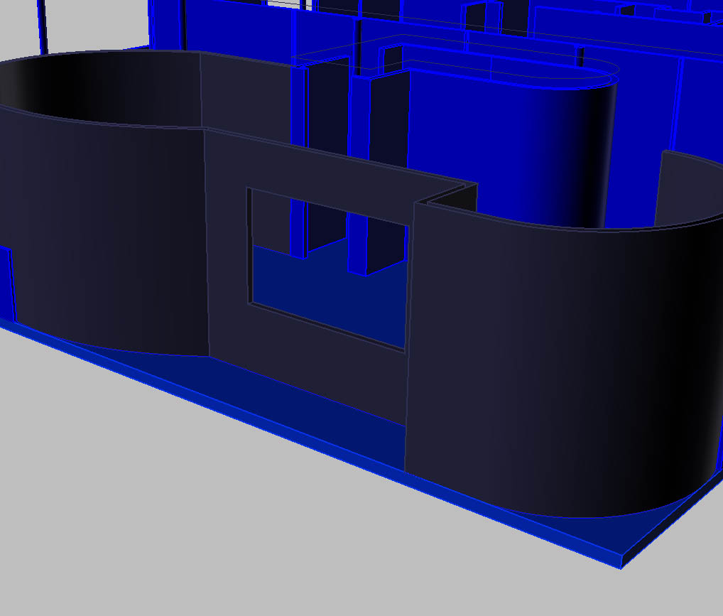
Use the West Elevation to measure the opening in the curved wall atrium on the roof. Repeat the steps used to cut the windows in the first floor to make this opening according to the measurements in the elevation drawing.
Make blocking above doorways
Create blocking above doorways (8' tall) using the same steps as the first level. There should be 4 total.
Extrude 2nd Floor Roof
Select the linework in the "roof " layer. PlanarSrf these curves and then ExtrudeSrf -.5" so that the foor extends 6" down to touch the 2nd floor walls.
Resources
- Modeling Villa Savoye
- A TUDelft tutorial that closely resembles this one.

