| Week 08 - Perspective | |
|---|---|
| Course | Arch 100a |
| Date | |
| Learning Objectives | This class will introduce architecture perspective drawings as means of representing spatial quality and experience of the design. The class will cover the technique of setting perspective view and making perspective drawings for a Rhino model, and showing examples of precedent architectural perspective drawings. |
| Agenda |
|
| Uses Tool(s) | |
Perspective Visualization
Last week, we introduced how to set up VRay for basic rendering. Today, we will learn architecture perspective drawing as a representation technique to depict the design idea. And further, we could use VRay to strengthen the perspective drawing through rendering.
- Recap

Perspective drawings
An architectural perspective is a subset of planar projection drawings wherein lines of projection begin with objects in the scene and converge at an imaginary "station point" that stands in for an observer's eye. Where these rays intersect a projection plane, an image is inscribed that approximates an image of the scene as it would be seen by the eye.
Types of perspective
Of the many types of perspective drawings, the most common categorizations of artificial perspective are one-, two- and three-point. The names of these categories refer to the number of vanishing points in the perspective drawing.

One-point perspective
- One-point perspective contains only one vanishing point on the horizon line. This type of perspective is typically used for roads, railway tracks, hallways, or interior view so that the front is directly facing the viewer. Any objects that are made up of lines either directly parallel with the viewer's line of sight or directly perpendicular (the railroad slats) can be represented with one-point perspective. These parallel lines converge at the vanishing point.
- One-point perspective exists when the picture plane is parallel to two axes of Cartesian scene – a scene which is composed entirely of linear elements that intersect only at right angles. If one axis is parallel with the picture plane, then all elements are either parallel to the picture plane (either horizontally or vertically) or perpendicular to it. All elements that are parallel to the picture plane are drawn as parallel lines. All elements that are perpendicular to the painting plate converge at a single point (a vanishing point) on the horizon.
Two-point perspective
- Two-point perspective contains two vanishing points on the horizon line. In an illustration, these vanishing points can be placed arbitrarily along the horizon. Two-point perspective can be used to draw the same objects as one-point perspective, rotated: looking at the corner of a house, or looking at two forked roads shrink into the distance, for example. One point represents one set of parallel lines, the other point represents the other. Looking at a house from the corner, one wall would recede towards one vanishing point, the other wall would recede towards the opposite vanishing point.
- Two-point perspective exists when the painting plate is parallel to a Cartesian scene in one axis (usually the z-axis) but not to the other two axes. If the scene being viewed consists solely of a cylinder sitting on a horizontal plane, no difference exists in the image of the cylinder between a one-point and two-point perspective.
- Two-point perspective has one set of lines parallel to the picture plane and two sets oblique to it. Parallel lines oblique to the picture plane converge to a vanishing point,which means that this set-up will require two vanishing points.
Three-point perspective
- Three-point perspective is usually used for buildings seen from above (or below). In addition to the two vanishing points from before, one for each wall, there is now one for how those walls recede into the ground. This third vanishing point will be below the ground. Looking up at a tall building is another common example of the third vanishing point. This time the third vanishing point is high in space.
- Three-point perspective exists when the perspective is a view of a Cartesian scene where the picture plane is not parallel to any of the scene's three axes. Each of the three vanishing points corresponds with one of the three axes of the scene. One-point, two-point, and three-point perspectives appear to embody different forms of calculated perspective. The methods required to generate these perspectives by hand are different. Mathematically, however, all three are identical: The difference is simply in the relative orientation of the rectilinear scene to the viewer.
Setup Rhino Camera for Perspective
When setting up your perspective views in Rhino, you want to think about how the camera is being used to helpfully depict your scene, for whatever purposes. You may wish to focus on circulation and get a close up of the stairs and passages into a space, or you may be interested in a sequence of spatial experiences as you move through a space or series of spaces. Regardless of your focus, a healthy understanding of how to set up your camera shots will be imperative in helping you reveal these various conditions clearly.
View Camera
To properly set you camera, you'll probably want to see where it is in 3d space. This is viewport specific, fyi. By simply typing "Camera", you can show the camera in the viewport you are in. The camera will show up in the other viewports, so make sure you open all 4 viewports to accurately see the camera.
For example, if we type Camera>Show, and we are in the perspective Viewport (shown below), the camera will appear in all three other viewports, exposing how it's framing the perspective viewport. If I type Show for another viewport, like Front View, the same thing will happen, and the other three viewports will pick up that camera scene.

You can
move
or
rotate
your camera by moving or rotating its control points.

Setting up Views/ Camera
- Eye level - this should be approximately 5 feet above the ground plane. You could create a 5' tall surface on your ground surface and use the OrientCameratoSrf command setting up the camera to lock on. Type OrientCameratoSrf and you will find out a white arrow follow you cursor, that indicate the position of the viewer(us).
- Use WalkAbout to lock your z-axis height. ( Make sure that you are still working in perspective viewport, you can tell form seeing the darker title box.) In WalkAbout mode, you can still zoom in an out along the 5' tall plane, as if you were walking around in 3d space. You can tell you're in WalkAbout mode by a small cross-hair in the middle of the screen.

- With WalkAbout turned on, you can also look around without zooming. You simple orbit around and the point you are at will be held, while the rotation around that point will be adjusted, like you were looking around without moving.To exit WalkAbout mode, type it again, or right click on the viewport title box, set view to another viewport.
- One-Point Perspective
- Please complete the protocol of setting up an eye level perspective for your space( followed the steps in the previous paragraph). Show the camera by typing Camera' and choose "show". Make sure that your picture plane is parallel to the dominate plane of the space you want to show, or the axis of vision is perpendicular to the dominate plan of your space.


- If you move the camera horizontally, you will keep in the one point perspective.
- Two-Point Perspective
- I. You can easily get a two point perspective view in Rhino 5 by switching the projection mode from perspective to Two Point perspective in Viewport Properties .

- II. :Manually, we could repeat the protocol of setting up one point perspective "without" keeping the axis of vision perpendicular to the dominant plane of the space, but we still keep the axis of vision on the same X-Y plane ( no Z-axis difference).

Lens Length
- The perspective camera in Rhino is set to 50 mm by default, replicated the approximate amount of perspective we see in real life. Look at this value in the Properties menu. As the value increases, the lines of perspective become more parallel. As the value decreases, the lines of perspective increase which could be helpful for an interior view. See examples below. In 100A studio, please keep your setting between 28-35 mm if there is no specific request.

-
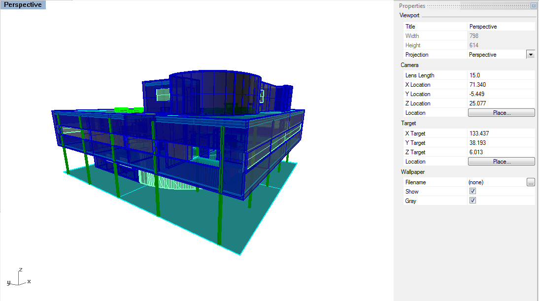
Lens Length at 15 - extreme perspective
-
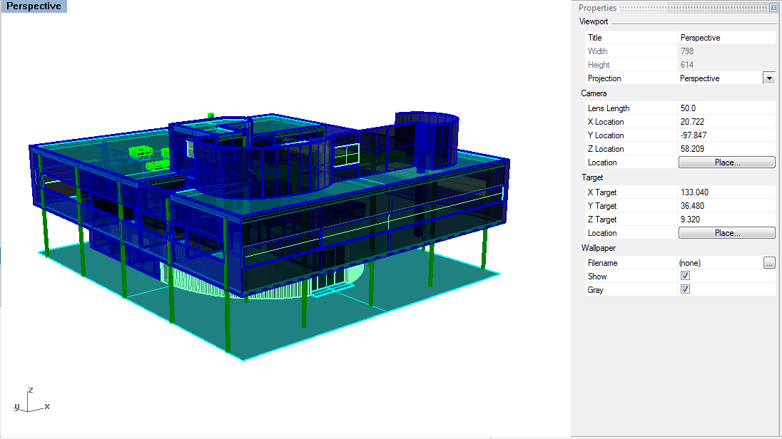
Lens Length at 50 - default
-
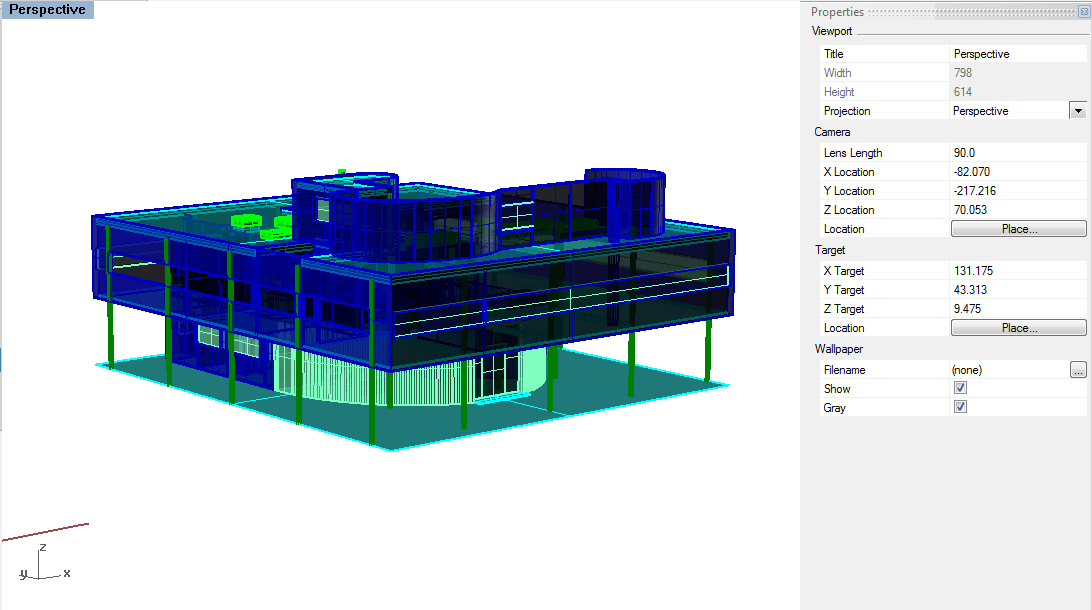
Lens Length at 90 - less perspective, close to Parallel view


Saved Views
As you should know by now, by clicking View>Set View>Named Views, you can Save your Camera View and access it again later. You may find that much of your model is not needed for the particular render your putting together. To save file space, you can delete the superfluous geometry and re-save the file as the render name or whatever you like. Below is an example of when a particular shot requires only a piece of the whole model.
(Left: Saved View, Right: Simplified Model (200C, 2011):

Conventions of Perspective Lineweight
Line weight
, or the visual lightness or darkness and width of a line, are conventionally employed in perspective drawings as follows:
First, as an object gets closer to the viewer, it should be drawn with a heavier lineweight. Lines for far object should be thinner than near object. Secondly, within each object, lines between the object and the space (object outline) should be the thickest to imply the depth behind, and then would be the corner line that shows the surface turn. The lines on the same surface or details should be drawn by the thinnest lineweight.

Precedent Slides
The precedents in these slides represent some of the possibilities of the sectional perspective drawing, including those with one vanishing point (1pt) and those with two vanishing points (2pt). Depending on your subject the section can be a simple poche or line work (early slides), or it can showcase how the space comes together, calling out building systems (second to last slide) and potentially the projection of space past the section plane (last slide).
Perspective Drawings in Architecture
Sectional Perspective
A section perspective drawing can offer more spatial depth and understanding to a project than traditional orthographic drawings that are kept in the parallel view. With the advent of 3d modeling programs like Rhino, creating a section perspective drawing can be relatively simple but may require some additional clean-up or re-modeling.
This workflow will go through how to set up a digital model to create the correct view and linework. In the session today, we just focus on the first half of the workflowhow. The technique of rendering the model for shadows, and further post-process in Illustrator and Photoshop for the finalized image product will be introduced later this semester.
- IMPORTANT--Lineweight rule in sectional perspective
- Section = 1.5 pt
- Profile Edge (building) = 1.25 pt
- Profile Edge (others) = 1.0 pt
- Corner Lines = 0.75 pt
- Far Lines = 0.5 pt
- Details = 0.25 p
