| Workshop 5a | |
|---|---|
| Course | Arch 200c |
| Date | 2012/11/01 |
| Learning Objectives | Introduction to Grasshopper |
| Agenda |
|
| Uses Tool(s) | Grasshopper |
Introduction to Grasshopper for Rhino
Grasshopper is a graphical algorithm editor designed for Rhino’s 3-D modeling tools. Unlike RhinoScript, Grasshopper requires no knowledge of programming or scripting to create parametric designs. The generation of software such as Grasshopper has presented an entirely new method of thinking about design issues.
Explicit History
It may be helpful conceptually to think of Grasshopper as an explicit history interface for Rhino - that is, an interface which shows the sequence of steps required to obtain a specific geometry. Rhino shows history entirely through the command input area and doesn't allow for dynamic paramaterization of steps; in other words, Rhino doesn't remember your steps along the way, it just gives you the final output of each command. Grasshopper, however, allows you to always go back and alter steps and parameters while seeing the consequences of each change. This ability changes the design iteration process by speeding it up exponentially, while allowing you to see the relationship of sequences of commands without destroying geometry.
While altering commands and geometry in Grasshopper, a preview of the result will appear in the Rhino model as a linked entity, also known as a BRep or a Boundary Representation. Only once a command has been "baked" will it become real geometry in the model.
Modules
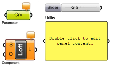
Grasshopper uses a variety of modules which can be interconnected to generate the Explicit History. There are 3 types of modules.
- The parameter
- The component
- The utility or special
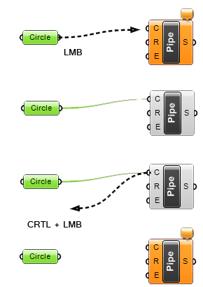
These modules can be connected with each other to form a network of relations and parameters. You can connect the parameters and components by clicking and dragging from the output of a parameter or component to the input of the component. To disconnect, use CTRL + Click and drag the connection in the opposite direction.
The Parameter
The parameter contains data, such as geometry or primitives. If a geometry type is selected as parameter, the geometry can be selected from existing Rhino geometry or can be made in the Rhino viewports. Examples of a parameter are curves, surfaces, points, numbers, text, and vectors.
When a parameter is defined by existing geometry in Rhino a relation is created between the geometry and the resulting BRep of Grasshopper - if the existing geometry is edited in Rhino, the resulting BRep of Grasshopper will also change. The new object can’t be edited in Rhino itself until it has been baked out of the Grasshopper interface.
This difference is important for the design strategy. If the design geometry has to be explored in an intuitive manner, a combination of editable Rhino geometry and resulting Brep geometry in Grasshopper can be an effective approach. If this approach is preferred, the decision has to be made what will be generated in Rhino as a basis of the design geometry and what will be part of the geometry defined by Grasshopper.
The Component
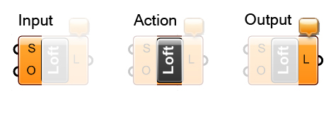
The component contains an action with an input and an output. In the component node an action is calculated and an output generated, and this output can be connected again with another component or utility. This production and manipulation of the resulting network of parameters, components, and utilities form the result of the associated design process.
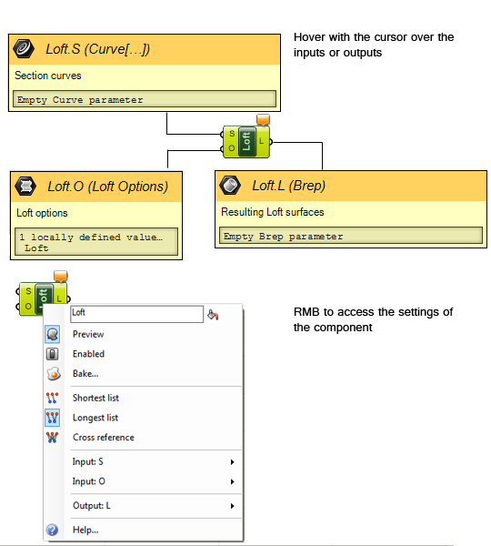
Hovering with the cursor over the input or output of the component will display the properties of the input or output. If you want to change the settings of the input or output use the right mouse button. The editable functionality, preview, and data management of the component can be accessed by the RMB click on the name of the component.
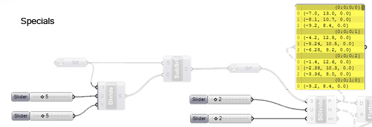
Specials
The specials contain a variety of functions which support the easy access and manipulation of the network. We can in some cases also use a Special for the input or output of a component. The most used are:
- Number slider
- The Panel
The number slider will enable you to define a number within a certain range and type. If you want to be able to move a curve of a loft, you can add a transform component to the curve and manually define the transformation with the help of the slider. The panel will give you feedback on the output of the components. This can be of use when you want to explore the list you want to edit.
Interface Feedback
The Grasshopper interface gives visual cues to the state of the definition. Colors of modules represent the state of tose modules in the definition:
- Orange: The module is empty (if a parameter) or does not have all required input (if a component) or has warnings
- Gray or Black: The module is fully defined with no errors
- Green: The module is currently selected
- Red: The module contains errors that need to be fixed.
While editing in Grasshopper, preview geometry will be shown in the Rhino model. The color of the geometry will represent different states:
- Blue feedback geometry means you are currently picking it with the mouse.
- Green geometry in the viewport belongs to a component which is currently selected.
- Red geometry in the viewport belongs to a component which is currently unselected.
- Point geometry is drawn as a cross rather than a rectangle to distinguish it from
Rhino point objects.
In-Class Exercise: Working in Grasshopper
Related Workflows
Resources
- Installing Grasshopper
- For this workshop, we will be running the latest WIP version of Grasshopper - 0.9 Revision 14. If you already have an older copy installed, please update using this installer .
- Grasshopper Primer
- Great resource for those just starting to learn Grashopper.
