| Drawing to Scale | |
|---|---|
| Architectural documents are drawn at a specific ratio relative to the actual size of the designed work. | |
| Part of | Drafting Board , Plotters and Printers |
| Part Type | Method |
| Screenshot |

|
Drawing to Scale in Architecture
Architectural drawings are drawn to scale so that relative sizes are correctly represented. The scale is chosen both to ensure the extents of the building will fit on the chosen sheet size as well as representing the required amount of detail given the type of drawing at hand.
For example, at scales appropriate to site drawings (1/32"=1' or more), buildings be simply represented by their overall outline, or "massing", with no detail of interior walls or spaces. At a scale of 1/8"=1' (1:96 or metric equivalent 1:100), walls are shown only as simple outlines relating to the wall's overall thickness. At a larger scale such as 1/2"=1' (1:24 or metric equivalent 1:20), layers of materials that make up the wall construction are depicted. Construction details are drawn to an even larger scale with even more detail, showing structural or aesthetic connections, and in some cases full scale (1:1).
Scale drawings enable dimensions to be measured directly off of the page using an architect's scale or a given graphic scale. On a 1/8":1' scale drawing, the 1/8th divisions on the ruler can be read off as feet. Still, because of reproduction errors, it's important to remember to include figured dimensions on the drawings that would be used for construction.
Scaled drawings are often produced and read using an architects' or engineers' scale .
Typical Drawing Scales
Imperial Scales
Under the Imperial system of measure, scales are marked as a ratio of x inches-to-the-foot (typically written as x"=1'-0"). For example one inch measured from a drawing with a scale of "one-inch-to-the-foot" is equivalent to one foot in the real world (a scale of 1:12) whereas one inch measured from a drawing with a scale of "two-inches-to-the-foot" is equivalent to six inches in the real world (a scale of 1:6). This should not to be confused with a true unitless ratio (inches to inches) .
The following ratios appear on a typical architect's scale:
- 3"=1'
- Three inches to one foot, 1:4 scale ratio
- 1 1/2"=1'
- One-and-a-half inches to one foot, 1:8 scale ratio
- 1"=1'
- One inch to one foot, 1:12 scale ratio
- 1/2"=1'
- One-half inch to one foot, 1:24 scale ratio
- 3/4"=1'
- Three-quarters inch to one foot, 1:16 scale ratio
- 3/8"=1'
- Three-eighths inch to one foot, 1:32 scale ratio
- 1/4"=1'
- One-quarter inch to one foot, 1:48 scale ratio
- 1/8"=1'
- One-eighth inch to one foot, 1:96 scale ratio
- 3/16"=1'
- Three-sixteenths inch to one foot, 1:64 scale ratio
- 3/32"=1'
- Three-thirty-seconds inch to one foot, 1:128 scale ratio
Metric Scales
Under the Metric system of measure, scales are marked as a direct ratio without reference to a base unit - drawings indicate both the scale of the drawing and the unit of measure being used.
The following ratios appear on a typical architect's scale:
- 1:1
- 1:2
- 1:5
- 1:10
- 1:20
- 1:50
- 1:100
- 1:200
- 1:500
- 1:1000
- 1:1250
- 1:2500
Appropriate Level of Detail
Based on the scale you used to represent your project, different levels of detail will be required to allow the drawing to read as an architectural space. In the examples below, you can begin to see how detailing can affect the quality of a drawing set. At a scale of 1/8":1' (1:96), walls are shown only as simple outlines relating to the wall's overall thickness, and we only need the basic geometry of fixtures and furniture. At a larger scale such as 3/8":1' (1:32), layers of materials that make up the wall construction are depicted, and more intricate detail is added to our fixtures and furniture.

-

Xeros House, Upper Level Plan
-

Burton Barr LibraryElevation


The Xeros House by Blank Studio (above, left) is residence of about 3,000 sf, and requires much more detailing than Will Bruder's Burton Barr Library (above, right) of 280,000 sf, nearly 45,000 sf on the shown floor plate alone.
Details of Construction
It's easy to get carried away with detailing, but it is important to keep in mind the intended purpose of the particular drawing you are working on. As an example, see the window plans below. The drawing at 1/8"=1' would probably appear as part of an overall building plan, where the specifics of detailing, visible in the last window drawing at 3/4"=1', would not only not be useful but would also become a messy blur of lines. This may sound intuitive, however, as a designer moves in the digital realm, where modeling and drawing happen at 'full scale', one can fall into the trap of over-detailing, at the expense of the larger picture.
-
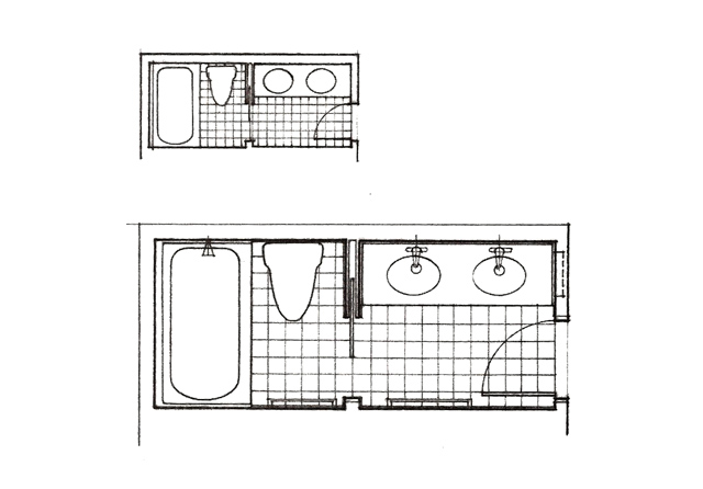
Fixtures Detailing
-

Window Sections at Various Scales

