|
Creating an Oblique Drawing using 2D AutoCAD or 2D Rhino |
|
|---|---|
| Screenshot | |
| This workflow will walk you through how to create a plan oblique using 2D drafting software. Plan obliques project the three dimensions in such a way that the plan remains true, and can therefore be measured. If constructed in a certain way, heights are also measurable. | |
| Uses Tool(s) | AutoCAD 2012 , Rhinoceros |
Plan Oblique
"Oblique projection is one of three major types of projection drawing. The images that emerge from oblique projection belong to the pictorial family of paraline drawings but are distinct from the isometric and dimetric views that develop from orthographic projection. In oblique projection, a principal face or set of planes in the object is oriented parallel to the picture plane as in orthographic multiview drawing, but the image is transmitted by means of parallel projectors oriented at any angle other than 90 deg to the picture plane.
"Oblique drawings show the true shape of planes parallel to the picture plane. Onto this [primary] view, [the two remaining views are attached and projected into the drawing]. This yields a three-dimensional image that represents what we know rather than how we see. It depicts an objective reality that corresponds more closely to the picture in the mind's eye than the retinal image of linear perspective. It represents a mental map of the world that combines plan and elevational views into a single expression."
(Francis D.K. Ching, Design Drawing )
Francis D.K. Ching has many books on drawing which explain these concepts in detail for those interested.
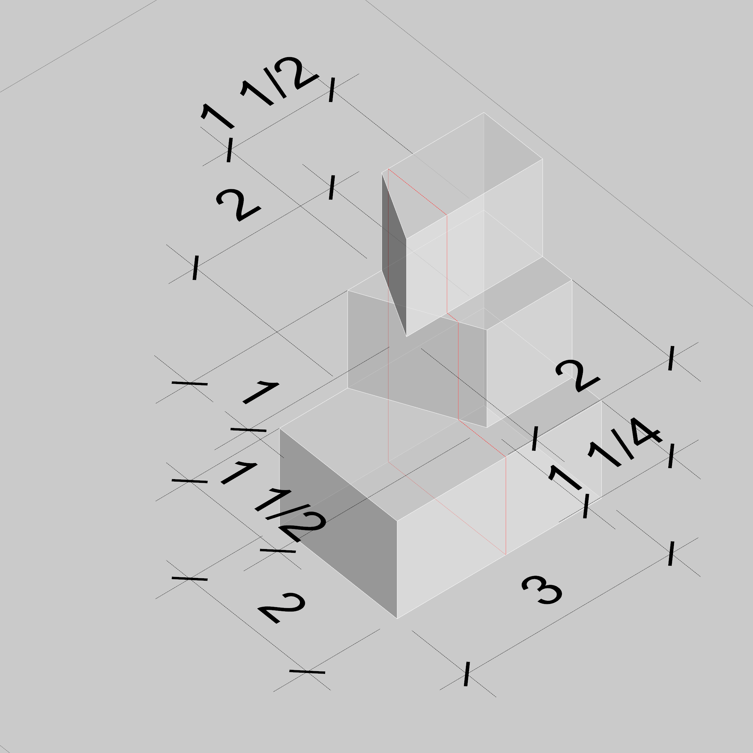
To follow along with this workflow, please download this file , which will give you the necessary plans. We will be making a plan oblique drawing of the mass below.

Steps
Rotate Plans to the Desired Angle
The first step in making a plan oblique is deciding what angle is best suited to your needs. Generally, smaller angles place more emphasis on the vertical elements and larger angles place more emphasis on the horizontal dimensions. However, this is not a hard rule. The image below gives some sense not only of the angle of plan rotation but also the scale of vertical elements, which we will discuss later.

For this exercise, let's take these plans and rotate them by 30°. To rotate type in rotate in either AutoCAD or Rhino and then follow the instructions in the command line - select the objects to rotate by highlighting them with your cursor and clicking, click on your base point which could be anywhere, and then type in 30 so that you control the exact rotation angle.

Offset Plans "Vertically"
To create the illusion of having 3 dimensions, we will offset the plans from each other by a fixed amount. The amount by which we offset the plans is variable, but conventionally it is either to scale, 3/4 height, or 1/2 height. For example, if you are drawing a plan oblique of house with two floors that are 10' apart and the drawing is at 1/4" = 1' - 0" scale, the floors would be separated by either 2 1/2" (to scale), 1 7/8" (3/4 height), or 1 1/4" (1/2 height).
Using full scale height or 3/4 height often looks more skewed than necessary, so let's offset our plans by 1/2 height. Since we are working at 1:1 scale and the height of each level is 1", we will offset the plans by 1/2".
To do this, join each plan so you have three polylines (select all segments of the line and type join) and then drag the second 'plan' to the corner of the first, and then move up by 1/2". Repeat with the third 'plan' but this time move up by 1". Here, "up" refers not to the vertical z axis, but rather to the y axis (think up on a sheet of paper). In this example, our reference point needs to be the uppermost corner, since that is the point all plans have in common.

Connect Corresponding Parts
Now we want to draw vertical lines from each corner to the next level. In our example, all "walls" are vertical, which means we can copy the three plans vertically by 1/2" to create the upper bounds of each level. Then we just connect each corner to the corresponding one immediately above it. If the walls are not vertical, the method is still the same, but the connections will not be vertical lines. Instead they would be skewed.


Fix the Line Weights
This last part is potentially the most complicated. If you have been working in using one line weight, you must now go through and split lines, trim edges, and the reassign lines to their proper line weight.
First, determine which lines must be split into different parts. Generally, this is done when a line is now behind something else in the drawing.

Lines behind some geometry must be made hidden, profile lines must be made heaviest, fold lines medium weight, and texture lines the lightest.

Plot
After plotting using correct line weights, your final plan oblique should look like this!

