|
Mapping a Complex Physical Form Using the Loft Method |
|
|---|---|
| Screenshot | |
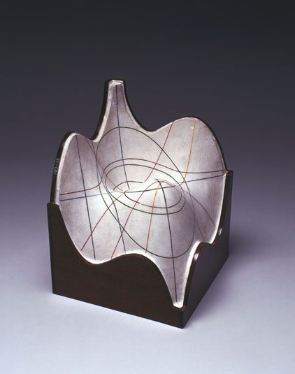
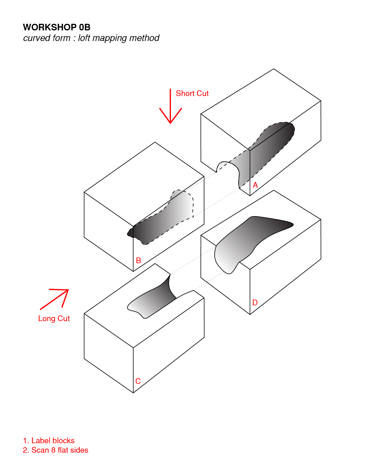
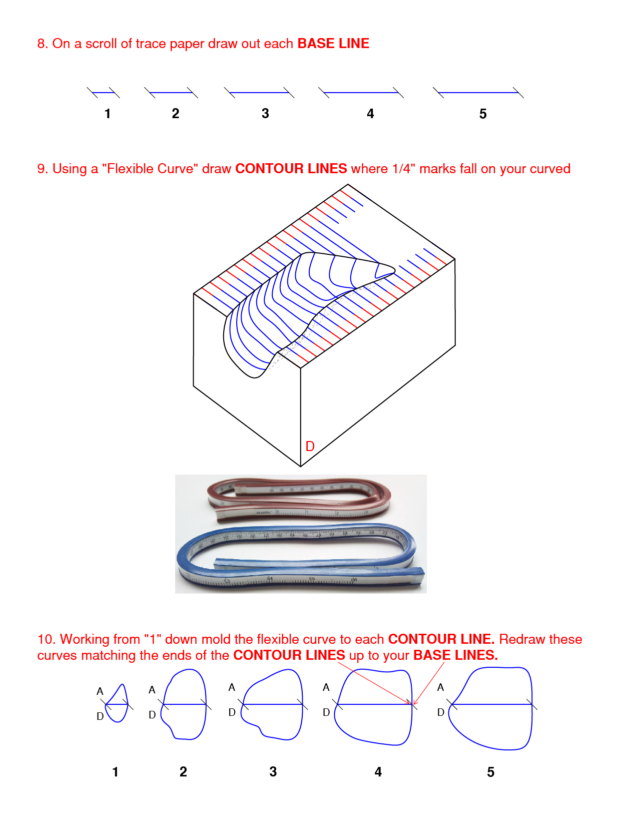
| This workflow presents a method for modeling a complex plaster surfaces in 3d by tracing curves on the physical model using a flexible ruler, transferring these curves into Rhino3d by scanning and tracing images, and finally generating lofted surfaces. | |
| Uses Tool(s) | Rhinoceros |
Download contour mapping PDF
Steps
Step 1
Step 2
Step 3
Step 4: Bringing traced artwork into Rhino
In order to begin to model your form in Rhino you will need to scan all of your contour drawings to bring them into Rhino.
See the first two steps of the Tracing 2d Drawings in Rhino workflow.
Step 5: Drawing 2d Curves
Download Drawing 2d Curves Rhino File: Workshop_0B_Modeling
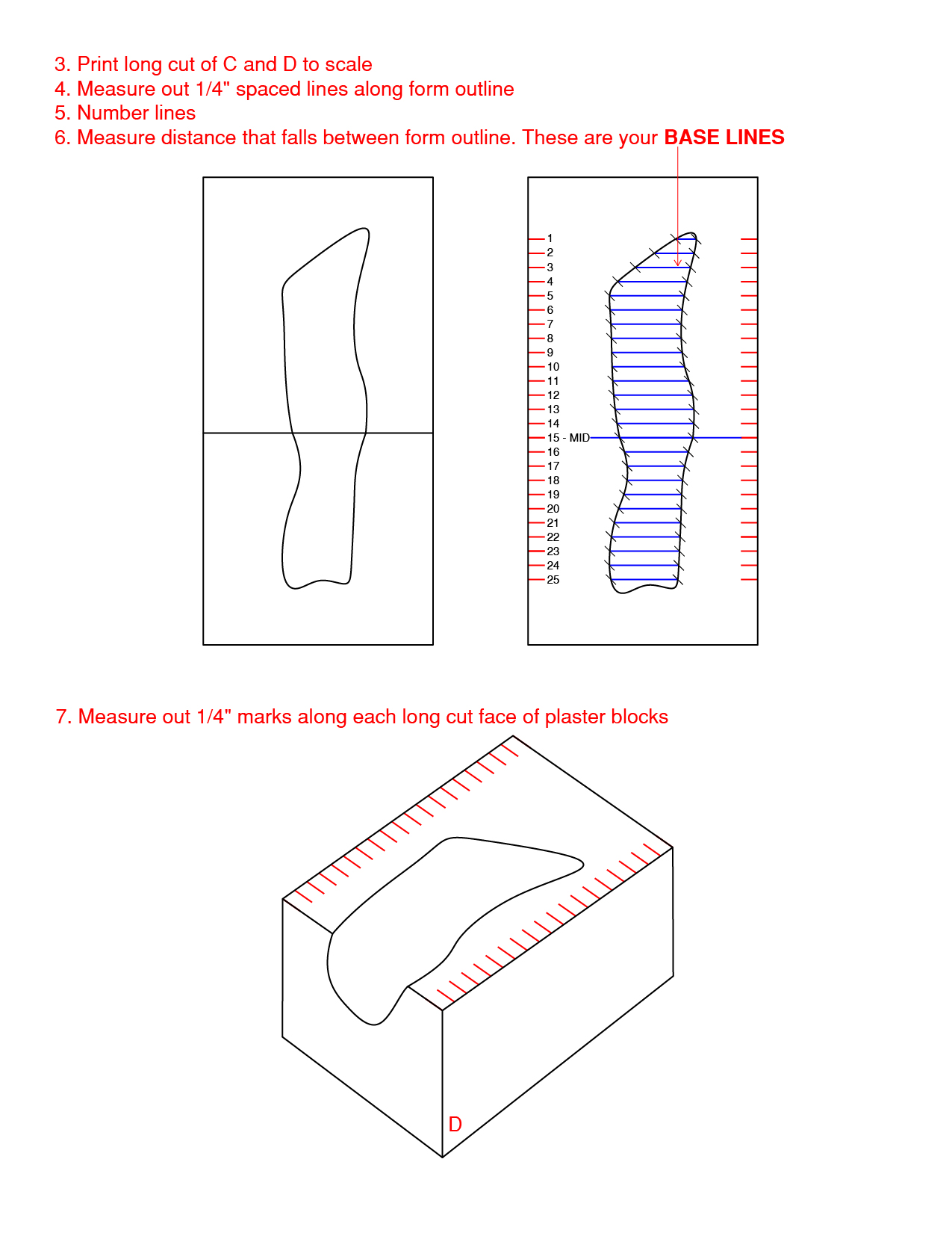
BASE LINES
To begin 2d drawing we will start by working exclusively in TOP view. Assure that your units are correct by typing “units” in the command line. Set model units to “inches” and distance display to “feet & inches”. Before drawing each contour curve first draw your BASE LINES, which were measured out in Step 3. Your BASE LINES need to be as accurate as possible and should be drawn on top of your scans but NOT traced from scans. They should be drawn using the line tool, exact measurements are typed into the command line. Select line tool -> click first point -> type measurement in command line -> enter -> click second point -> click space bar to stop drawing. Italic text
To ensure the lines are straight and aligned with one another turn on “ortho” and “SmartTrack” found at the bottom of the screen. To use “SmartTrack” hover over the end of the last line drawn, as you move your curser to the right a construction line will appear. Draw your next line along this construction line.

CONTOUR CURVES
There are many different ways to draw curves in Rhino. In this workshop we will use “interpolate point curve” which can be accessed via the bank of command icons on the left side of the Rhino interface. It is not the icon circled in the screen shot below. Click on the small triangle in the corner of the icon circled below and several more curve drawing options will appear. Hover over the icons to see their names and click on the "interpolate point curve" icon.
Turn off “Ortho” and “SmartTrack”. Turn on “Osnap” and check only the “End” box. This will make sure that your curve lines up exactly with each end of your BASE LINES because they will "snap" to the end of the BASE LINES when you start drawing.
To draw each curve click on the “interpolate point curve” icon, click your first point on the end of your BASE LINE, following points along your scanned curve, and last point on the end of your BASE LINE. Click the space bar to finish the curve.
If your curves to not match up as well as you would like you can edit an existing curve by turning on and manipulating its control points.
BASE DRAWING (from “long cut” scan)
In order to rotate and move your CONTOUR CURVES into the correct position you must make a measured BASE DRAWING from all of the sides you have scanned that have curved forms. “Ortho” and “Osnap” on.
Trace one line along the length of the drawing, at your number “1” quarter-inch mark -> snapping to the end of this line trace a perpendicular line to the end of your drawing -> select first line (horizontal line) -> type “arrayCrv” in command line -> select second line (vertical line) as base point -> set “distance between items” to .25 and “orientation” to “no rotation” -> click ok

Step 6: Rotating and Moving 2d Curves
- You may want to edit your original CONTOUR CURVES in the future. Before rotating and moving your curves make a duplicate of the original by highlighting all the curves, dragging with the mouse, and clicking the “alt” key.
ROTATE
So far we have only been working in TOP view. In order to rotate and position your BASE and CONTOUR curves we will also work in RIGHT and PERSPECTIVE view. “Ortho” on, “Osnap” end and near on. Select all CONTOUR and BASE CURVES -> open right view port -> type rotate in command line -> draw a horizontal line anywhere on the screen -> click and rotate objects 90 degrees counter clockwise.
MOVE
We will move each contour curve pair and base line into place in PERSPECTIVE VIEW. “Ortho” off, “Osnap” end and near on.
Select first pair of curves -> type move in command line -> click on the end of the BASE LINE -> move curves over the base drawing and position along first line.
The word “NEAR” will appear as you are moving the curves and hovering over the horizontal lines of your BASE DRAWING.

Step 7: Surface Modeling using Contour Curves
At this point, we're ready to create surfaces from the traced and oriented contour curves we've extracted from our physical model. There are many ways of creating surfaces in Rhino, each of which may or may not be appropriate to the particular geometric situation you find yourself in. Rather than explicitly outline a linear workflow here, we'll simply introduce a few modeling operations that may work for you.
Download Modeling with Contour Curves Rhino File: Workshop_0B_Modeling2
All your CONTOUR CURVES are now in place and are essentially the ribs for a polysurface that will be created using the LOFT, SWEEP, or SURFACE command.
LOFT - Fits a surface through selected profile curves that define the surface shape.
http://docs.mcneel.com/rhino/5/help/en-us/commands/loft.htm
SWEEP2 - Fits a surface through a series of profile curves that define the surface shape and two curves that define the surface edges.
http://docs.mcneel.com/rhino/5/help/en-us/commands/sweep2.htm
NETWORKSRF - Creates a surface from a network of crossing curves. Note: All curves in one direction have to cross all curves in the other direction and cannot cross each other.
http://docs.mcneel.com/rhino/5/help/en-us/commands/networksrf.htm
EDGESRF – Creates a surface from two, three, or four selected curves.
http://docs.mcneel.com/rhino/5/help/en-us/commands/edgesrf.htm
Step 8: Add “Hole End” Contours
In order to build a continuous surface around a hole in your plaster form you will need to map two additional contour curves located at each end of the hole. These curves should have a mid-point where the lines pinch together (where the plaster becomes very, very thin). Be sure to measure where these are located in relation to the 1/8” curves you have already drawn. Place these two new curves in line with your other contour curves. Copy these two curves to a hidden layer of another color.
Step 9: Place “Hole” Contour
In order to create intersecting surfaces around a hole in the form you will need to also trace and scan the outline of the hole. Trace the hole on your physical model with a thin piece of trace and scan/trace this curve like you have for the other contour curves. This curve, of course, is not two-dimensional like the other contour curves and although you first draw it in 2d it will be manipulated so that it takes a more three-dimensional form. Once your hole is drawn rotate and move it so that it is roughly in the correct position in relation to your contour curves. Turn on EDIT POINTS on and drag one point to each tip of surrounding CONTOUR CURVES. Make sure there is a control point on each end of the hole to attach to the new end CONTOUR CURVES you have added in. You may need to add a control point to do this.
Step 10: Build Surfaces
Because the surface of your form is irregular and because of the hole in the form you will build surfaces in sections and join the sections once you are finished modeling.
Use the hole contour to split the contour curves that cross it, including the end contours you have added (make sure you have copied these curves to another layer before splitting them). Use the last contour curve in each section to also split your base curve.
Use the end contours to split the HOLE CONTOUR.
Select the CONTOUR CURVES, HOLE CURVE, and BASE CURVE in one section and use the “NetworkSrf” command to create a surface. If there is an error, first check to make sure that all of your CONTOUR CURVES are touching the BASE CURVE and HOLE CURVE on each side. If not this can be corrected by turning “edit points” and “Osnap” on for these curves and moving the end point so that it touches an edge curve (be sure to work in both top and perspective view).
Continue to work in sections using the “Split” and “NetworkSrf” commands to create surfaces.
You will need to use the “EdgeSrf” command for the ends and odd parts of your forms.
If there is a bent or “L” shape that you are having trouble modeling you may need to break it into sections but using the “line” and “split” tool and then using the “EdgeSrf” command.
When you are finished modeling all the surfaces “Hide” the contour lines by selecting them (you can right click on a layer and select “select objects”) and typing the “Hide” command. Select all the surfaces you have modeled and type “join” into the command line.
Step 11: Build Rectangular Plaster Mass
Now that you have the organic form created by the balloon cast you can model the rectangular plaster around it. Using the “Rectangle” tool draw a rectangle the same dimensions as your plaster. Place this rectangle using a reference point so that it is in the correct location in relation to the curved forms and on the same plane as your base lines (double check this in front view).
Select the rectangle and working in front view use the “ExtrudeCrv” command and type -3” or whatever your depth is. Select the form and type the “Cap” command. This will create a solid rectangle around your form. You now need to “Trim” the areas of the rectangle that your form cuts out. Select the rectangle and type the “Explode” command. The rectangle is now 6 separate surfaces. Working in top, front and side view select the rectangle plane you want to trim and the base lines you will use to trim. Type “Trim” in the command line and click the surfaces you want to remove.
Once you have completed trimming the unwanted surfaces hide all contour curves, select the surfaces and use the “Join” command.
Step 12: Crop Area of Interest
Once your form is constructed you may want to isolate a particular area of interest. You can do this with the “Trim” command. In front view draw one large plane, this will act as a TRIMMING PLANE. In top view copy, rotate, and move this plane so that it frames your area of interest. The TRIMMING PLANES must cut completely through your form. Check this in perspective view.
Working in top view select your form and the TRIMMING PLANES. Note: it may be easier to work one at a time, also change your view mode to “wireframe”. Use the “Trim” command to delete the parts of your form you want to remove. Once the solid parts have been removed, select the TRIMMING PLANES and trim the areas extending beyond the form.
Working in front and side view “Trim” the parts of the TRIMMING PLANES that extend above your form. “Join” everything.
Common Problems
Modeling Intersecting Forms
When two or more forms intersect, the resulting geometry can be difficult to approximate.


