|
Creating Buildings for a Contextual Scene in Rhino |
|
|---|---|
| Screenshot | |
| When rendering a building, modeling the surrounding buildings will give the rendering context. This tutorial explains how to turn a photograph of an existing building into a realistic texture map in Rhino. | |
| Uses Tool(s) | Rhinoceros , Photoshop CS5 |
Steps
The workflow is missing some elements: top summary, resources, common problems. The workflow would benefit from static images to reinforce the methods discussed in the videos.
This workflow can be completed using just one software tool - it would be better described as a "method" of Rhino
Make a Mapping Texture
To make a mapping texture, choose a photograph of the facade of the surrounding building. Try to use a photo that is relatively straight and without any distortion. In Photoshop , use the Lasso tool and click on the corners of the facade to trace the boundary of the building. Right click on the selection and click on Layer via Copy to create a new layer with just the selection on it. Click on the eye icon next to the Background layer to turn its visibility off.
The facade will most likely still be slightly skewed because of the angle at which it was taken. The image must be transformed in order to fit the rectangular plane of the 3D model. Before transforming the image, it is helpful to use the rulers to make horizontal and vertical guidelines so that it is easy to tell when the image has transformed into a rectangle. To do this, click on the ruler and drag a guide into the editing space. Then, Click on the layer while pressing down the Control key to select the image. Click Edit->Free Transform , and then right click on the image and select Distort. Drag the corners of the image until it is a rectangle. Use the Crop tool to edit the image to fit within the boundaries of the guides. Save the edited image as a .jpeg file.
Mapping the Texture to the Building
For an introduction to texture mapping in Rhino, see this workflow .
Build a simple box to represent the building. To map a single facade, explode the box into separate faces by selecting the box and using the Explode command. Select the surface on which the photo will be mapped and move it to a separate layer by right clicking on the layer name and selecting Change Object Layer.
Open the Material Editor for that layer by clicking on the circle in the same row as the layer's name in the Layer panel. Check the box for Texture and specify the Map file as the image that was just created. Right click on the viewport name and select Rendered so that the texture is visible.
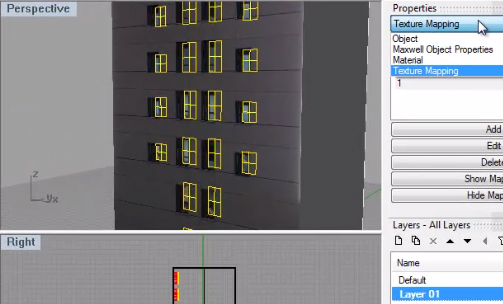
To fit the texture to the surface more precisely, it is helpful to change the mapping style to box mapping . To do this, make sure the Properties panel is open (use the Properties command). In the drop down menu, select Texture Mapping, and then select Show advanced UI. Click Add to add a new channel. Scroll down in the panel to the General settings, and for Projection select Box from the drop down menu to change the mapping style.
Making Windows
Making Windows using MakeHole
The texture can be used as a template to build an accurate 3D model of the building so elements, such as the windows, are in the correct place. The windows will correspond with the windows in the texture, giving dimension and depth to the texture so it renders more realistically. In the front viewport with ortho on, trace the outlines of the windows. In the top viewport , select the rectangles and move them so that they are in front of the surface. Use the MakeHole command, select a rectangle as the cutting object, and then select the depth of the hole in the surface behind the rectangle. This is a more tedious method because only one rectangle can cut at a time.
Making Windows by Extruding
A faster way to create windows is to extrude the rectangular outlines. First, project the rectangles to the facade using the Project command. Use the rectangles to split the surface . Delete the surfaces that are obscuring the window opening. Select the rectangles and use the ExtrudeCrv command to extrude to the proper depth (make sure capping is off). Manually cap the extrusions by selecting the rectangles where the window would be and using the PlanarSrf command. Select the surface and the windows, and use the Join command to ensure that the box mapping works correctly. With this joined surface selected, go to the Properties for Texture Mapping, and add a new box mapping channel.
Adjusting Window Transparency
Adjusting the transparency of the window surface will make the windows look more realistic. Explode the joined surface, and then only select the window surfaces. In the Properties panel, select Material from the drop down menu, and choose Basic under "Assign by." Scroll down to "Basic" and change the Transparency to 60 (the greater the number, the more transparent the selected surfaces will be).
After mapping all facades of the building, it is ready to be rendered with surrounding buildings in a context shot.
