| Week 6 - Architectural Plans + Sections | |
|---|---|
| Course | Arch 100a |
| Date | 2012/10/05 |
| Learning Objectives |
This class will focus on architectural conventions for plans and sections. An overview of lineweights and drawing standards will be presented. The workflow will show the process of making plans and sections of a digital model, with emphasis on organizing lineweights and editing the linework to produce clean presentation drawings.
In addition, we will review last week's exercise and surface manipulation tools. |
| Agenda |
|
| Uses Tool(s) | Rhinoceros , Illustrator CS5 |
Week 5 Recap
- Surface manipulation tools
- Cutting in and adding objects to a surface
First way - Blending the site by connecting side edges : Cut into the site using a larger bounding box than the building itself. Create a Rectangle and then Trim the site itself. Then use the EdgeSrf command to connect the site to the foundation of the building, one side at a time.
-
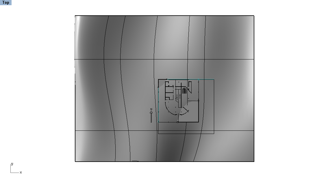
Create a rectangle over the existing site
-
Trim the site in the Top View
-
Use the EdgeSrf command to connect the site from one edge to another
-
Repeat the command for all four sides


Second way - Using serial sections to loft new ground surface pieces : Split off a whole section of the site using either projected linework or a CutPlane . Then create serial sections with this pieces along the x or y axis using the Contour command. Make sure the end edges are duplicated using the DupEdge command. Once you have the skeleton of the split surface, Delete the surface piece. Then transform the linework to suit your needs, either by moving the control points POn or moving the entire line down to the edge of the building. Once the linework is create, Loft the lines to create the final surface.
-
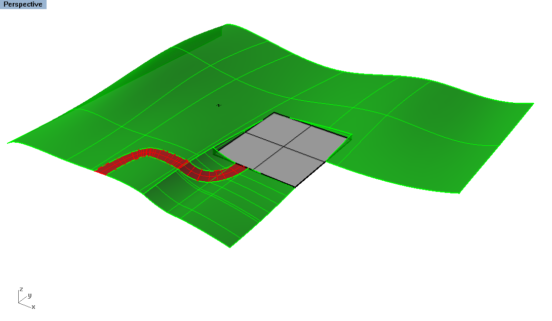
Split out a piece of the site surface
-
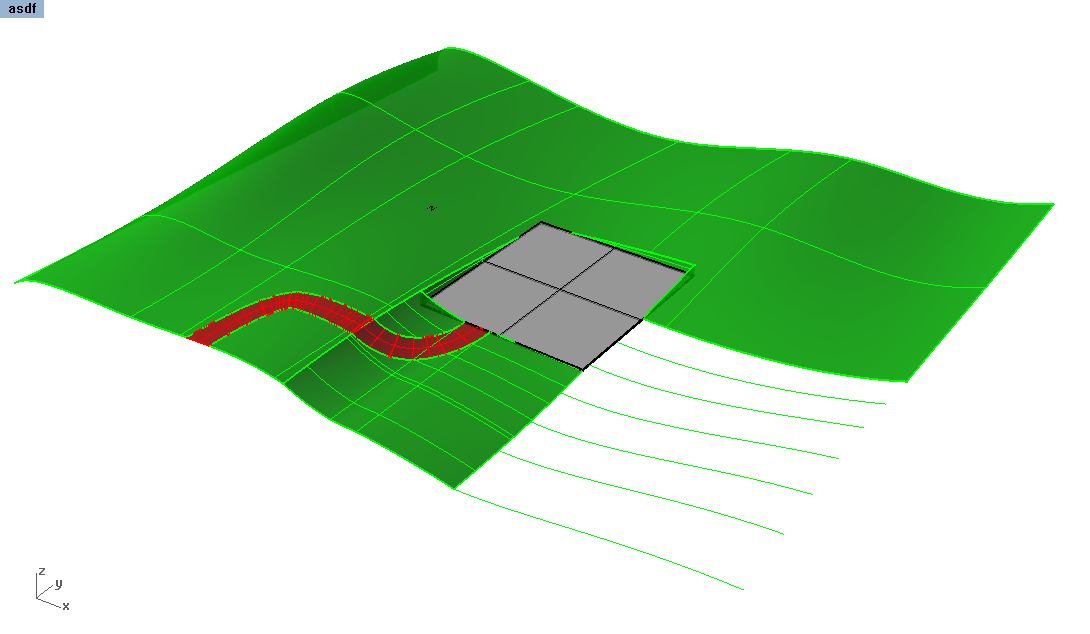
Use the Contour command to create serial sections
-
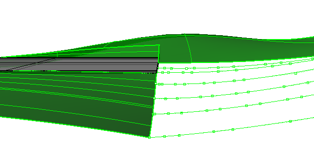
To edit just the end points, put control points on
-
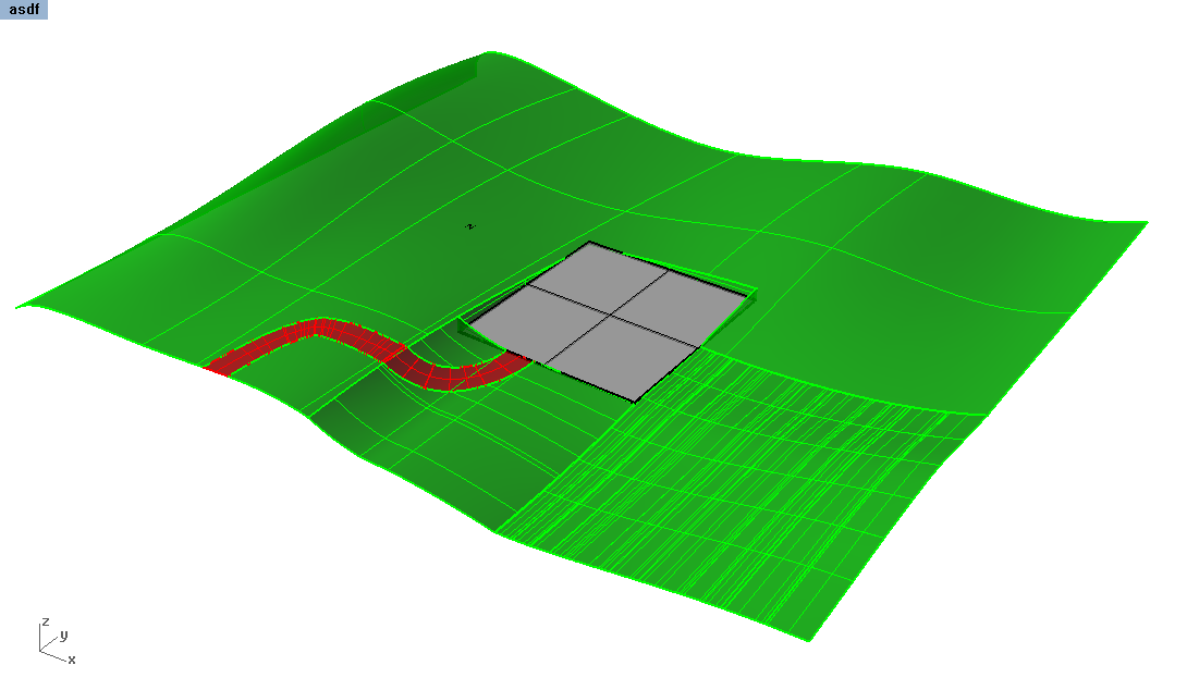
Re-loft the lines to create the final surface


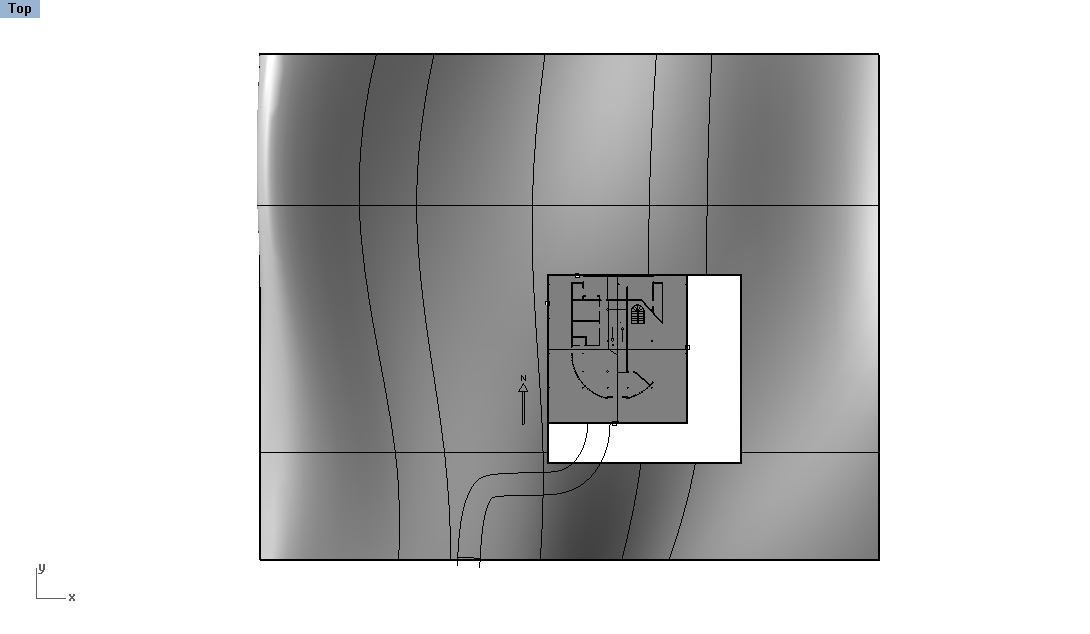
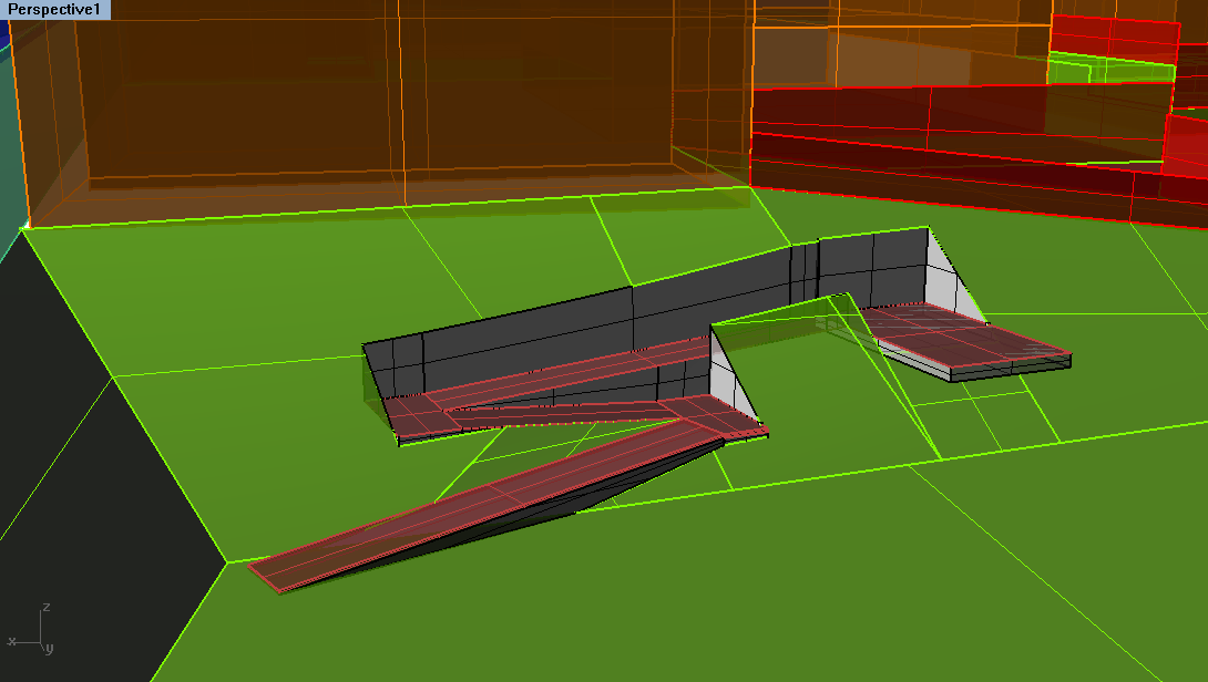
Example: Ramp in site
-
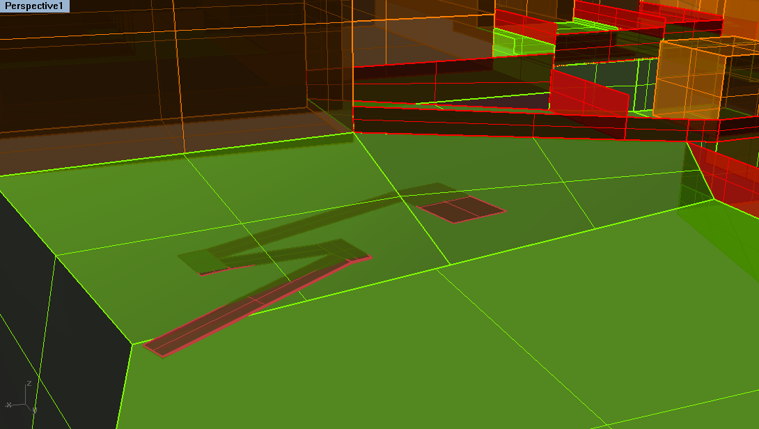
Building in site - partially above, partially carved into the site.
-
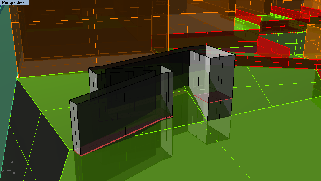
Extrude the edges of the object outline to find intersections with the ground plane
-
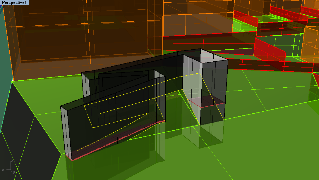
Use the Intersect command with the previous extrusions
-
Use the intersecting linework to trim out the ground surface.
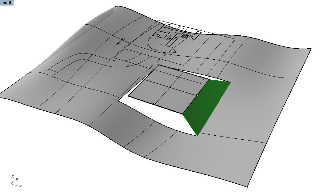
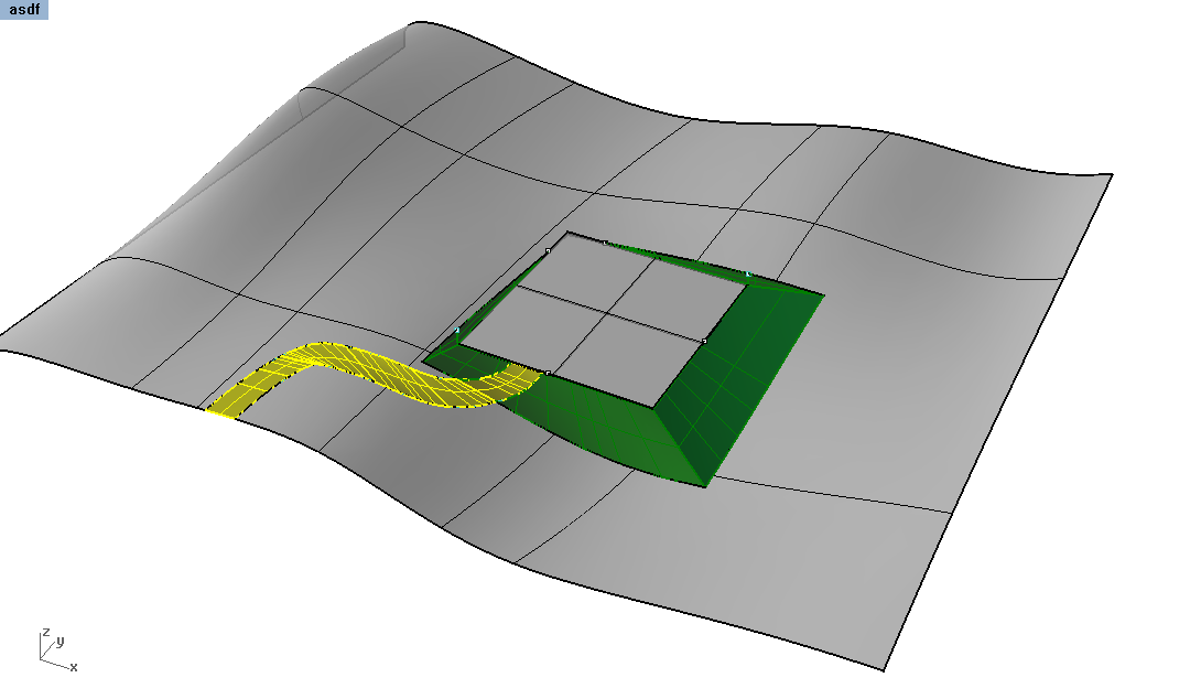
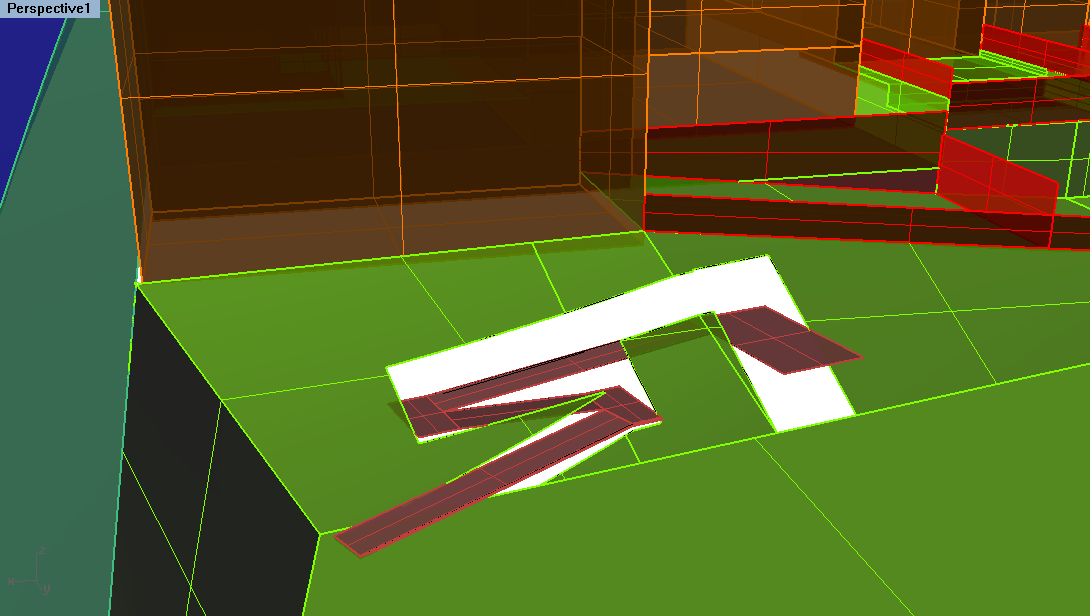
-
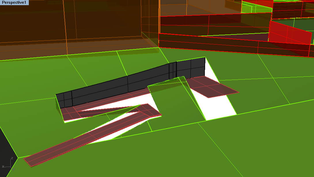
Retrace outlines of the edges to patch in holes where you carved out, using EdgeSrf, PlanarSrf or Extrude.
-
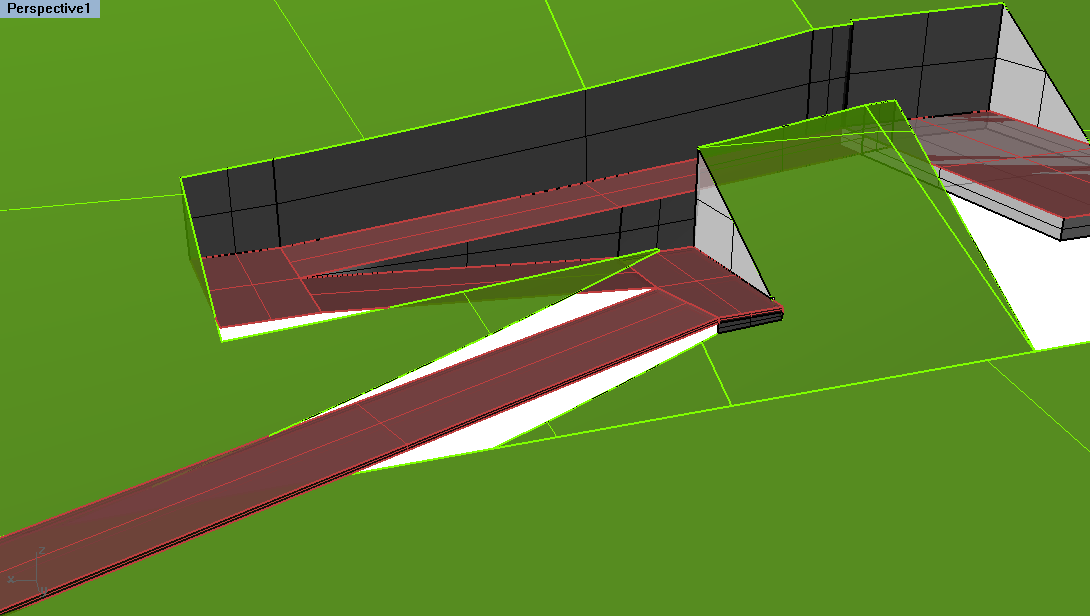
Split + Trim the landscape as needed and create new surfaces.
-
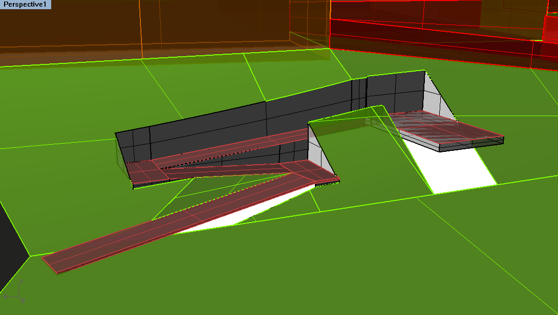
For areas that are not carved out, rebuild the surface as needed.
-


Demonstration on Pt. Bonita
To show more of the concepts you'll need in typical studio work, here is a Pt. Bonita site model to demonstrate how to complete 3 different modeling styles: above the landscape, on the landscape, and in the landscape.
Plans + Sections
Using your digital model, the process for making plans and sections will be very similar to how you made drawings of your double negative project with added emphasis on architectural standards and conventions.
The images below will help you to understand the concept of orthographic drawings in the architectural context with basic examples of each drawing type.
-

Orthographic Projection Concept Illustrated
-

Section Concept
-

Example of Elevation


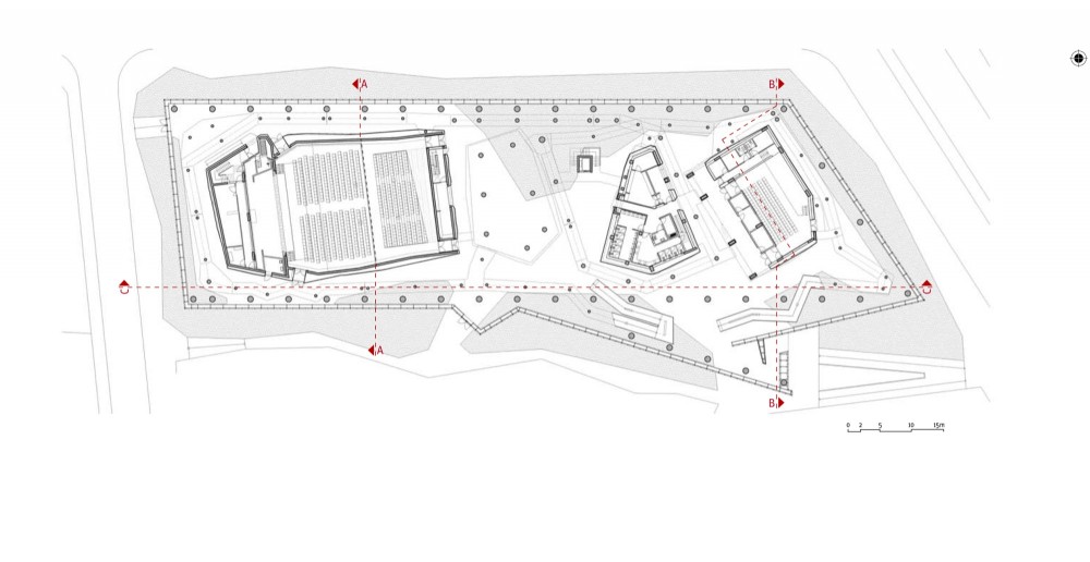
Cutting Plane
- Plan (Cut plane created in the Right or Front view)
- Plans should be cut 3 feet above the ground floor.
- Section (Cut plane created in the Top view)
- Sections should be cut in areas that most emphasize your concept and best illustrate your project
Lineweights
Majority of the time working on your drawings will probably be spent cleaning up the Make2d output and assigning lineweights. These lineweights are crucial in helping your drawings read properly. Notice the differences in the drawings below:

Use your experience from past projects to coordinate lineweights, especially regarding what lines were too thick (no thicker than 2 pt), what lines were too light and didn't show up (less than .12 pt will not print) and what hierarchy helped your drawing read properly. Refer to the lineweight distribution below for reference:

Adding Architectural Standards
In addition to cleaning up linework and designating proper lineweights - additional details will need to be added to your drawing to exemplify architectural standards. These include editing stairs and ramps to denote direction, noting the above elements and adding detailed elements such as door swings and furniture.
- Stairs
- When cutting a plan, about five steps should be left in the Make2d output - hoewver this is not how stairs are typically drawn. Rather than a horizontal cut line, stairs are most often drawn with a diagonal cut line. The remainder of the stair is then shown by dashed lines representing what is above. Stairs below are in full view and should be shown as a complete set of steps.
- Ramps
- Ramps are also often cut off at an angle to represent the section cut with large diagonals placed in the width of the ramp. Dashed lines should show the ramp continuing into the space above.
-

Basic graphic convention for ramps.
-
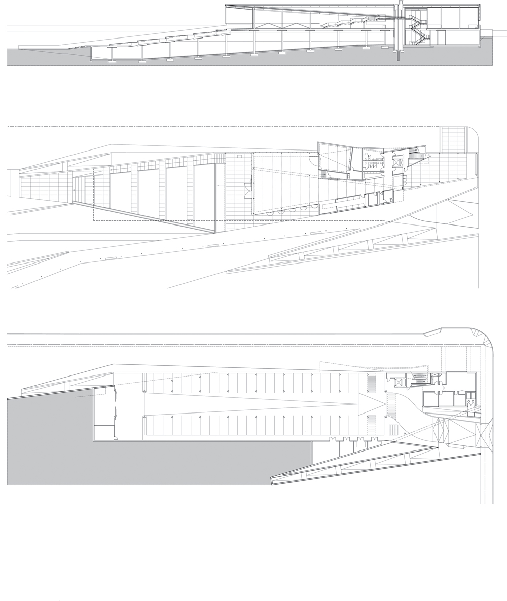
Here's a good example of the Olympic Sculpture Park in Seattle, WA
-
Another example by Emre Arolat. Notice the dashed lines of the ramps above.


- Above content
- Important elements that are above the cut line also need to be represented as a dashed line. These include overhangs, the continuation of stairs and ramps, etc. Rather than deleting half your Rhino model when creating plan cuts, be sure to hide it so that you can refer to it later. The above linework should not be confusing - be sure to simplify the linework to a simple outline of the object.
Exercise
- Fitting a Design into an Existing Site Model
- Students must re-model the site itself to fit the stair and ramp model on top of it.
- Final model should be uploaded to bSpace by the end of class, Friday October 5.
Additional Workflows
These workflows are here to help over the weekend with drawing:
- Creating clean drawings from a 3d model .
- Very similar to the workflow creating drawings of the double negative, this takes you through the steps to produce plans and sections of a building model.
- Designing with and Finalizing Extracted linework
- This workflow goes beyond the basic process of Make2d to discuss the importance of editing and adding on to linework to produce more detailed architectural drawings.
Other Common Problems
- Imprecise Linework + Model building
- Snaps : Having OSnaps such as End and Midpoint on are extremely crucial in being precise when drawing in Rhino. Having ALL the snaps on though can lead to imprecise model making. Be sure to have Near OFF.
- All forms in the 3d model should have some element of THICKNESS.
- No material is infinitely thin as the single surfaces in Rhino. Be sure to OffsetSrf or Copy surfaces over to represent the thickness of the material.
- Difficulty zooming into model
- Every so often you will need to reset your view when you are zooming in on parts of your model. Two important ways to do this:
- Refocus your view on that object using the Zoom Selected option. This is especially helpful when you are having trouble zooming in further and it seems like the camera isn't moving anywhere.
- Change your Lens Length. With the Properties menu open, change the Lens Length to something smaller. The default is 50 mm which is replicating how we see perspective in real life. Making this smaller will increase the perspective, and allow you to better see in small spaces.
Resources
- Francis D. K. Ching, “Architectural Graphics,” (Wiley, 2002)
- Mo Zell, “Architectural Drawing Course.” (Quatro Publishing, 2008)