| Week 9 - Advanced Rhino Modeling | |
|---|---|
| Course | Arch 100a |
| Date | 2012/10/26 |
| Learning Objectives | Overview of Rhino modeling thus far, highlighting common mistakes and how to avoid them. Discussion of modeling for different purposes - creating drawings, diagrams or renders. Presentation of advanced Rhino editing tools such as C-Planes. |
| Agenda |
|
| Uses Tool(s) | Rhinoceros |
Recap from Last Week
- Lamination Speed Tip
- Discovered in section last week, you can use the Shear command to quickly separate contoured linework. After using the Contour to create the serial sections, Join all the linework that was created. Then select all of the lines (not the model) and type in the Shear command. In your Right viewport, first click on the bottom of the model. Then click directly above it (but not on the model, to make sure that your line is perfectly vertical). Then move to the Top viewport to view the linework moving away, sheared into place. Use your judgement for proper spacing for your next click.
Rhino Modeling
We have previously discussed various method of Rhino modeling. Today will emphasis working with precision, using Rhino as a tool for Design and a discussion of common problems and how to troubleshoot them.
Maintaining Precision: Working with Construction Lines + Planes
- Using the Automatic Grid
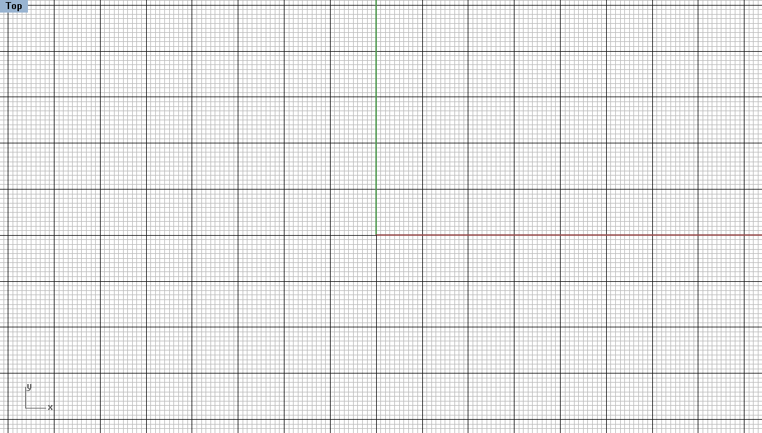
- Rhino automatically places construction lines in the form of a grid in the background. This grid can be edited by using the Grid command.
- Snap Spacing - Changes how often it will snap to points on the grid when GridSnap is on
- Minor Line Spacing - Changes spacing of the Minor line (which can be colored differently in the Properties tab
- Major Line Space -Changes the spacing of the Major line (which can be colored differently in the Properties tab
- Extents - Changes the overall size of the Grid
- Show Grid - Toggle this on and off to hide or show the grid in each viewport
- Show Grid Axes - Shows or hides just the Grid Axes
- Show World Axes - These axes are helpful when orienting yourself in the perspective viewport
- Apply to - Toggle this to apply your new settings to either the Active Viewport, or all the viewports
- Creating your own Construction linework
- Rather than using the grid, you can also create your own construction linework on a separate layer. This allows more flexibility - you can create linework along all three axes, at separate angles and at different intervals.
- Create one line and use the Copy to continue it along a certain direction. Use the options FromLastPoint and UseLastDistance by typing U and F to simply keep clicking in one direction.
- Create one line and use the Array command. Type in the quantity for the X, Y, and Z direction. Either click on a distance in the drawing or type in a distance for the space. Press enter and it will automatically create the linework.
- Create linework according to your site model or site data. Continue working on a separate layer and create linework on existing surfaces so that you are working on actual surfaces. Use the command InterpCrvOnSrf or ExtractIsocurve to creating linework on existing surfaces.
- Using C-Planes
- C-Planes are another extremely helpful tool when trying to work on a specific plane or angle within a Rhino file. Rather that working off to the side and later projecting linework, you can edit the C-Plane so that the linework is automatically being projected onto a certain plane or angled according to a predominate angle (so that the Ortho command can be kept on). Hold down the C-Plane bar in the basic toolbar to see the variety of options for editing the default C-Plane.
- Origin - Changes the location of the origin.
- Elevation - Change the Z-Location (height) of the C-Plane. Good for when working on different floors of a building, for example.
- Object - Orients the C-Plane to an existing Object such as a surface. Centers the origin on the surface and orients the entire plane along the object as well.
- Curve - Orients the C-Plane perpendicular to an existing curve.
- Rotate - Rotate the C-Plane to existing geometry. This is especially helpful when using the Ortho command for geometry that is not along the default C-Plane axes.
- Vertical - Creates a vertical C-Plane according to a specified point.
- 3-Point - Creates a C-Plane along the surface of 3 selected points.
- World - Returns to original, default C-Plane locations
- Use NamedCPlane to Save a useful created C-Plane or to return to a previously saved C-Plane
- Video Examples - Check 'em out!
- Set CPlane Origin
- Because each CPlane has a grid, moving the origin of the CPlane will move the origin of the grid. This is useful if snapping to the grid is turned on as it aids in modeling more precisely.
- Set CPlane by X-axis
- This aligns the X-axis of the grid to any axis chosen in the model. It is useful for rotating the CPlane.
- Set CPlane to Object
- Setting the CPlane to a surface ensures that the subsequent objects are in plane with that surface. This may also rotate the CPlane.
- Saving the CPlane
- The position of the CPlane can be saved for easy access later.
Different ways of Modeling
There are different ways to model dependent on the different purposes or outcomes of the final model. These may affect the overall precision or extents of detail in the final model, as well as how you prefer to work (in 3d or 2d).
Design Modeling
Using 3d modeling programs in design is a great way to think just beyond the 2-dimensional drawing. Immediately, a concept can be encapsulated in terms of volume and form. Important elements to consider:
- Scale. Rather than working at a scaled drawing where it may be easy to understand the scale of a person or door, the scale varies as you zoom around a model in Rhino. It is important to maintain an understanding of what scale you are working in and how it relates to a person or the site.
- Cleanliness + Precision. Using clean, precise linework will produce the best water-tight model. OSnaps should be limited to End, Midpoint, Point, Intersection and Perpendicular. Layers should be organized according to different surface types versus linework.
Using Models for Drawings
Oftentimes 3d models come out too detailed for proper orthographic drawings, and must be cleaned up extensively in Illustrator or Rhino. Save yourself the trouble and the time and clean up your model before exporting or using the Make2d command - and remember that you can always turn off layers or use Save As to create a new model you can manipulate without interfering with the rest of your completed model. Thing to consider:
- Precision. Make sure surfaces and lines are properly matching up to avoid more work cleaning up the Make2d linework. Remove duplicate objects so that no lines are overlapping.
- Organization. Layer management is key in efficiently producing the proper linework for drawings, such as a layer for Section linework.
- Level of detail. Consider the scale of the drawings you are producing when it comes to how detailed the model should be. Also question what element could be drawn in or added to the final drawings rather than 3d modeled.
Using Models for Renderings
Your tendency may be to feel that you must include as much detail as possible in your 3d model in order for it to appear correct in renderings, but it is most of the time unnecessary. Extra geometry in your file, that must got through raytracing to determine how light reflects off of it and into the camera, will add to your render time and hinder you from producing everything you need for your project. Remember that renderings can be post-processed in Photoshop to have complex materials that would take many hours to render. Things to consider:
- Removing Unwanted Elements. Different views will require different surfaces or parts of the model to be on . For example, an interior render may require you to turn off or trim off parts of the building. Save the original model before editing a version for a specific render.
- Efficiency. Some elements might be easier to texture map or produce in Photoshop rather than creating a detailed object in Rhino.
Modeling for Physical Models
This was largely covered last week. As mentioned, often the 3d model will change drastically to cater to the scale and detail involved in a physical model. Rhino offers many helpful tools to quickly produce drawings for fabrication, but the detail involved will likely be much simpler than models for drawings or renderings. Things to consider:
- Scale. Consider the scale of the original model versus the scale of the final model and material used for fabrication.
- Organization. Working between the model and the production drawings in the most smooth, efficient manner (using different layers, keeping linework flat and clean).
Presentation : Modeling Examples
- St. Marys Cathedral
- De Young Museum
- Seattle Public Library
Workflow
- Modeling a Kayak using a Jig
- This workflow emphasis the use of creating construction lines to reproduce a kayak from existing naval drawings. Precision in tracing and placing the linework is key in recreating the object.
Exercise
- Modeling a Kayak
- Practice the workflow by modeling the kayak in this exercise.


