| Week 02 -Designing Space and Form | |
|---|---|
| Course | Arch 100a |
| Date | 2013/09/06 |
| Learning Objectives | 1) Modeling space and form as a complementary and subtractive process via three dimensional spatial construction. 2) Cutting through our model to produce 2D linework for orthogonal drawings. 3) Translating 2D linework from Rhino into Illustrator for final editing. |
| Agenda |
|
| Uses Tool(s) | Rhinoceros , Illustrator CS5 |
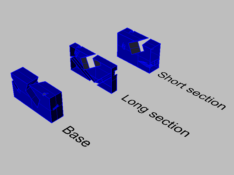
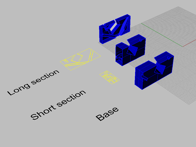
Access a sample Rhino Double Negative here: Double Negative .
Access sample Illustrator Line Work here: Illustrator Linework .
Access the 3D modeling examples here: Examples .
Please find some Digital Lab related course information here: ARCH 100A Housekeeping
Meet The Rhinoceros
(10 minutes)
The Basics
Background
Rhino is a 3-D modeling software commonly used for industrial design, architecture, marine design, jewelry design, automotive design, CAD / CAM, rapid prototyping, product design as well as the multimedia and graphic design industries. Many plugins work with Rhino that do everything from parametric modeling to photo-realistic rendering.
Learning Rhino is like learning to speak a new language, and like learning any new software, can be very frustrating at first.
NURBS
 Non-uniform rational basis spline (NURBS) is a mathematical model commonly used in computer graphics for generating and representing curves and surfaces, and is the basis of 3D modeling in Rhino. Rhino can also deal with rational surfaces and meshes. While the math behind NURBS is complex, the important thing to remember is that the geometry in Rhino is defined by control points that you can manipulate.
For an in depth look at NURBS see: Context:Overview of NURBS Geometry or visit TUDelft's site wiki page here .
Interface
Rhino works with both text based commands typed directly and point-and-click visual menus. For a comprehensive list of commands access http://docs.mcneel.com/rhino/5/help/en-us/commandlist/command_list.htm
As you use various commands, you will notice that Rhino will guide you through the command, asking for various inputs along the way in the command bar.
PC vs. Mac
We will be teaching and working with Rhino on PC. If you are running Rhino on a Mac there is a good chance you'll run into issues that we cannot take the time to remedy. Additionally, the interface is different on each and it may be difficult to follow along.
The Basics
Viewports
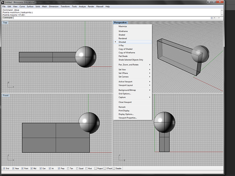
Like most CAD programs, Rhino works with multiple viewports. Double click on the title of the viewport to maximize it (and minimize) or right click to change the way geometry is viewed (wireframe, shaded, etc.). Zoom in and out with the wheel on your mouse, and pan by holding down the right mouse button and moving your curser. For more information access Tool:Part 74655Osnaps
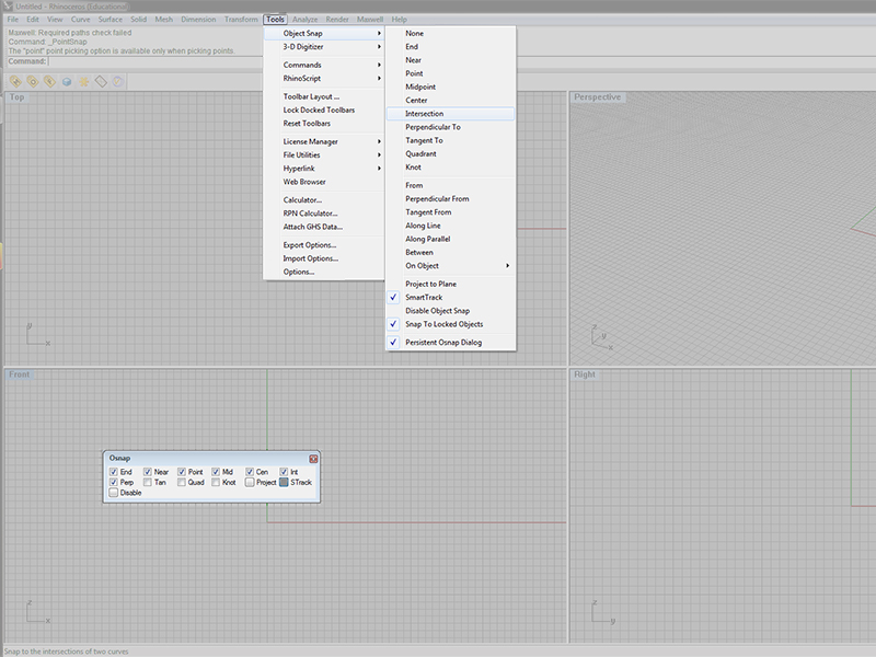
'Object Snaps' refer to your ability to determine what type of geometry your cursor selects (end points, middle points, etc.). They are an important part of modeling accurately, and you should be constantly toggling these on and off. When you open Rhino you should have the "Osnap" menu open. If not you can access it from the "Tools" menu or just type Osnap.Layers
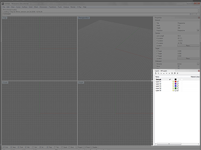
Using layers is critical to keeping models organized and clean - especially when we begin to create 2D linework from complex shapes and export to Illustrator. Access your layer menu by typing Layer.Properties
The properties window gives detailed information for selected geometry - most importantly what layer your geometry is on. Access the properties menu by typing Properties.
Modeling
(35 min) For our purposes, and in general, it is best to have an idea of what you want to create before you begin modeling in Rhino. Simply experimenting in Rhino will rarely result in compelling results. This means you should spend time with pencil and paper prior to entering Rhino space.
Basics
Explore the basic these basic commands under the "Transformation" menu.
- Move, copy, rotate, delete, mirror,
Lines and Curves
Lines are composed of points, and may be a single "Line", "Polyline", or "Curve". This can be a confusing part of Rhino - for even though the commands differentiate between a "Line" and a "Curve" all linework is considered a curve by Rhino. For instance, the "SelCrv" (select curves) command will select all curves, polylines, single lines, rectangles, circles, etc. in your file.
There are many commands for producing curves. Access these options under the "Curve" menu or curve palette. Some of the most common and useful commands are: line, polyline, rectangle, circle and arc.
- "Curve" and "InterpCrv" will create 'free-form' curves, but the results lend themselves to less accurate modeling.
There are many editing commands for 2D linework. Some of the most useful include:
-
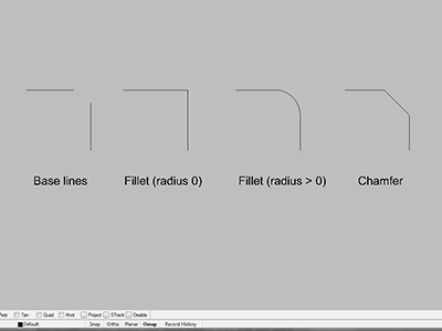
- Fillet : Add an arc between two curves and trims or extends the curves to the arc. If the radius is set to zero you will create a right angle.
- Chamfer : Create a line segment between two curves and trims or extends the curves to meet it.
- POn (points on): Display curve and surface control points for manual editing.
- Trim : Cut and delete selected portions of an object at the intersection with another object.
- Split : Divide objects using other objects as cutters.
Surfaces
There are various ways of modeling surfaces. You can access these options under the "surface" menu or tool palette.
Planar Surfaces
- Plane, Plane (Vertical), PlanarSrf, PlaneThroughPt, CutPlane,
- These are used to create a planar surface, and therefore require that foundation linework be planar. The 3-point option can be very useful when using the "plane" command.
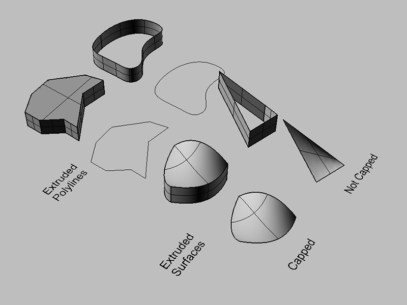
Extruded Surfaces
- ExtrudeCrv, ExtrudeCrvAlongCrv, ExtrudeCrvTapered, ExtrudeCrvPoint,
- When working from existing linework, such as a plan and section, these extruded tools are very easy to use and allow for high degrees of precision.
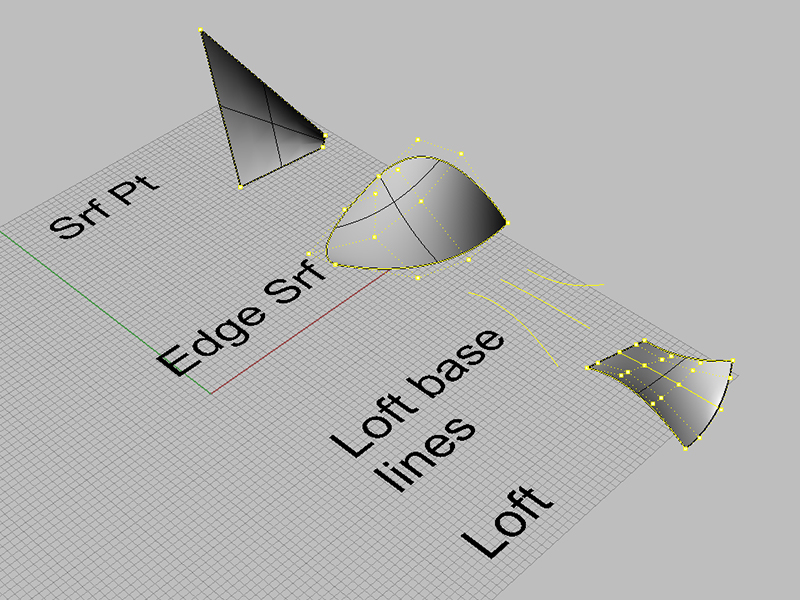
Non-Planar Surfaces
- SrfPt, EdgeSrf, Loft, Revolve, Sweep1, Sweep2
- When simple extrusions won't work, these tools allow more input. "loft" and "sweep" can be powerful generators of form, but require careful base linework.
Solids
In reality, there are no "solids" in Rhino. What we call solids are closed polysurfaces. This means that if you trim or split a "box" - you will see a hollow volume inside rather than a solid surface.
Stock Polysurfaces
Rhino can quickly create many geometric "solids" (rational surfaces) by clicking on the "Solid" menu or palette. These include:
- Box, sphere, cylinder and cone.
Extruding Polylines and Surfaces
- Another method for creating a "solid" is by extruding a Polyline . First create a closed curve (no gaps in the curve), either with multiple single lines, curves, or a polyline. Then use the ExtrudeCrv command (select the "cap" option to close the volume).
- Once you have created a surface, whether planar or not, you can extrude that surface with the ExtrudeSrf command. Notice that some of the options allow you to extrude in both directions, as well as adjust the direction of your extrusion.
Closed Polysurfaces
Finally, you can manually create polysurfaces by joining multiple surfaces. When doing so, it is important to get in the habit of making your volumes "watertight." That means - like a closed curve - there are no gaps in your polysurface. This is a good habit to follow in general, but will be very helpful when we generate 2D linework from our 3D geometries. "Watertight" volumes require much less editing in Illustrator.
Editing polysurfaces
These tools will be pivotal for creating your double negative space. We will cover just a few in detail - but you will find many more under "Surface Edit Tools" within the "Surface" menu and "Solid Edit Tools" within the "Solid" menu.
Boolean
Boolean operations will produce new geometry from two given geometries (sound familiar?). There are four different options, but using the Boolean2Objects command (also found under the solid menu) will allow you to select your geometries and then click through the four options. Hit space bar to select an option. Alternatively, if you know exactly what type of boolean operation you want you can type the command in directly.
- BooleanDifference : Subtract the volume of one object from another.
- BooleanIntersection : Create a new solid from a set of objects' intersected volumes.
- BooleanSplit : Split and close objects at intersections.
- BooleanUnion : Combine the volumes of two objects.
For more info on Boolean operations see Workflow:985407
Fillet & Chamfer Surfaces
Just like lines - we can fillet and chamfer surfaces with the FilletSrf and ChamferSrf commands.
3D to 2D
(15 minutes) One of the most useful commands in Rhino is Make2D. This allows us to capture the linework of our 3D geometries from any viewport and project that linework onto a 2D plane. See this workflow for an extensive treatment of this process.
Setup
Setup model & save copies
We will be literally cutting sections and plans through your geometry, so the first step in Make2D is to Copy what ever geometry you are going to cut so you always preserve an un-edited copy.
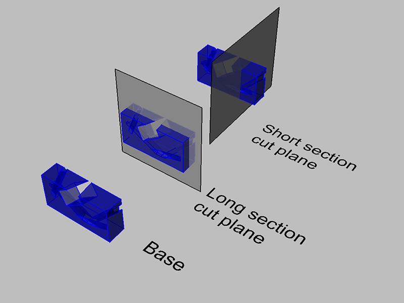
Section cut planes
The next step is to cut your model to expose plans and sections. To do this we must create the planar surface that will be used to cut your model. We do this with the CutPlane command. This will ensure a plane that completely bisects your model. Use the Ortho option to make sure your section plane is at a right angle relative to the viewport (or hold down shift when drawing the section plane).
Splitting and/ or trimming
After we have our cut plane, we will remove part of our model to expose the section or plan we wish to capture. We do this one of two ways:
- Split and Hide This option allows us to retain the part of our model we are going to hide while we Make2D . Use the Split command first to break our model into two parts. If you find that the model is not separating you may need to use the Explode command to split polysurfaces into individual surfaces. After you have split the model, Hide the geometry to one side of the cut plane. You can bring back hidden geometry with the Show command.
- Trim : This option simultaneously splits and deletes our unwanted geometry. Use the section cut plane as the cutting object, then select the geometry you wish to delete.
Make 2D
- For some tips and trouble shooting access Mcneel's site at Tips
Overview
The Make2D command captures linework in a selected viewport in relation to that viewport's construction plane and projects it as a two-dimensional drawing to the origin (0,0,0) of the X-Y plane.
This is the primary method to make orthographic drawings from a model, allowing one to export resulting linework as an Adobe Illustrator file.
Though Make2D is a versatile and extremely useful command, there are several known issues which can be helped or eliminated by following the general preparation instructions provided.
In general, you should spend some time editing your linework in Rhino - which can be much easier than Illustrator. Consider what your final product will be. Do you want to show hidden lines? How many lineweights do you want to incorporate? It is highly recommended you organize your linework onto layers in Rhino that will determine your lineweights when you export to Illustrator.
Preparation
- Simplify: Join all surfaces into polysurfaces insofar as possible - everywhere surface edges are concurrent, Rhino has to calculate two edges instead of one and see if there are overlaps.
- Use the Right Stuff: Make2D does not create 2 D drawings from mesh objects, only surfaces, polysurface, lines, curves, and points.
Intersect Surfaces
Rhino will not automatically generate linework where surfaces intersect with Make2D . You may therefore need to manually identify these instances and use the Intersect command to generate the curves to be captured for these intersections.
Position Your Model
Make2D acts as a camera, taking a snapshot of your model in whatever viewport is active when you execute the command. Position your model and view appropriately (if you are making a plan drawing of your building - the "TOP" viewport is likely the one to make active and execute the command in). To activate a certain viewport, simply zoom in and out of it and ensure that the position's text box is a different color from the rest.
If possible try to ensure that the geometry included in the Make2D stays inside (does not touch) the viewport boundary at all (this might be impossible for interior views).
Ensure Proper Objects are Selected
Turn off layers that contain unwanted linework and/or details. Ensure that duplicate geometry is hidden or deleted with the selDup command. If you are doing a close up of a model that contains geometry which is off screen, you can ensure that only visible objects are selected with the selVisible command.
Make 2D
Once this is all set you can execute the Make2D command.
2d Drawing Options
Once you type Make2D you will be presented with various options.
Drawing Layout
- Current View
- The view in the active viewport will be made into 2D lines. For instance, if the Perspective viewport is active, then that perspective of the model will be made 2D. This is useful for generating lines to overlay on a rendering. This is what we should use.
Options
- Show tangent edges
- Draws tangent edges of polysurfaces. Check this if it seems like some lines are missing in the drawing.
- Show hidden lines
- Draws the lines in the model that are obscured by other objects. The hidden lines usually show up as white in the drawing on the "Hidden layers" specified.
- Maintain source layers
- The output is placed on a layer with the same name as the input geometry. If this is not checked you can manually assign which layers corresponding linework will be assigned to.
Illustrator
(Class sessions)
Exporting/ Importing
To get our linework into Illustrator, we first must Export it from Rhino. When you use the Export command you can specify the Adobe Illustrator (.ai) filetype and then specify the scale. It is important to remember that the origin of your file (0,0,0) will be the lower left corner of your illustrator file, so you may need to move your linework prior to exporting.
Editing lineweights
For a discussion on conventions of sections and lineweights access Tool:Part 25270 and Tool:Part 306409
Open the exported .ai file in Illustrator. You will notice that the exported line work is positioned awkwardly on the page. To correct this we will use RULERS in order to adjust the dimensions of the ARTBOARD.
First, open rulers by selecting "View > Rulers > Show Rulers" from the top drop down menu. You will notice the a ruler tab opens along the top and left hand margins of your document. Note: the shortcut for opening RULERS is Control + r key.
Now, to adjust the artboard dimensions select the Artboard Tool from the left main toolbar. The shortcut is Shift + o . You will notice a bounding box appear along the edge of the artboard.
Before adjusting, we need to align the ruler with the edges of our artboard. To do so, move your cursor to the top left corner of the rulers and click and drag crosshairs to the top left edge of the artboard. You will notice that the ruler measurements now begin from the top left corner of the artboard.
- Rulers & Artboard
We can now see that our line work will comfortably sit within the margins of a standard 8.5" x 11" document. Using the bounding box, adjust the artboard accordingly. To move our line work back onto the artboard, Control + a , or SELECT ALL, and drag to the artboard.
We can center the our line work on the artboard by referring to our RULERS. Simple drag GUIDES from them onto the artboard. Since our document is 8.5" x 11", we will drag a GUIDE to 4.25" along the x-axis, and to 5.5" along the y-axis.
With the line work selected, use the bounding box to center the drawing on the artboard.
- Guides & Centering
Layers Panel & Color Panel
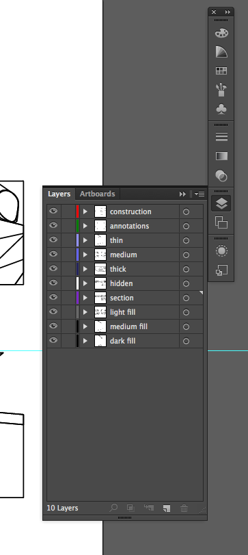
From the right tool bar, open the LAYERS PANEL. You can also open it by selecting, "Windows > Layers" from the top drop down menu.
Notice that the layers that we created in Rhino are preserved within our Illustrator document right down to the color that Rhino assigned to each layer.
- Rhino Layers Perserved
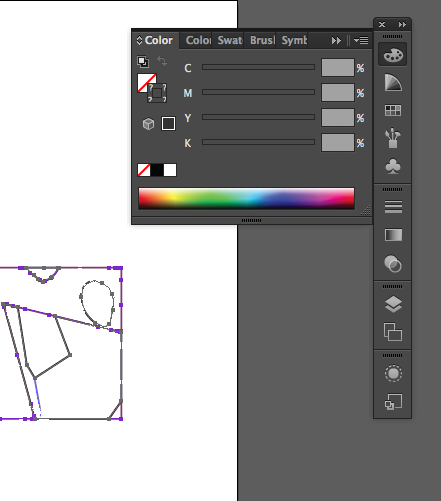
For our drawing we are going to want all of our line work to be black. We can quickly achieve this by, Control + a (select all) and opening the COLOR PANEL from the right tool bar. You can also open it by selecting, "Windows > Color" from the top drop down menu.
- Color Panel
Notice, the hollow box icon has question marks throughout it. This is the STROKE icon. Because we have all of our line work selected, and all of our line work is different in color, it cannot determine a single color to present. We can quickly chance all of our line work to black by selecting the BLACK BOX beneath the STROKE icon.
Organizing Layers
One fundamental difference between Rhino and Illustrator is how layers interact with one another. In Rhino, the sequence in which layers are organized does not influence our viewing of the content within them. On the other hand, in Illustrator (and Photoshop), the sequencing of layers determines what is visible and what is not. It is important to remember that if a layer is above another within the LAYERS PANEL, then its content is literally resting on top of the layer on the artboard.
We are going to be filling in our section cuts and elevations with color. If these layers are on top of our line work layers then they will obscure our ability to view the line work.
Reorganize the layer sequence within the LAYERS PANEL so the section and fill layers are beneath all of the line work layers. You can do this by manually dragging individual layers accordingly.
- Layers Organized
Adjusting Line Weights
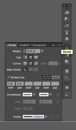
By maintaining source layers when making 2D and exporting from Rhino, we should be set to assign lineweights quickly. First we select all the linework on a given layer by clicking the circle to the right of the layer menu. Once all the linework is selected, we can got to the stroke panel dropdown and select a lineweight and stroke color.
- Stroke Panel
Adjusting Line Types
Within the STROKE PANEL you will notice a "Dashed Line" option box. We can use this option to assign our hidden line as dashed.
- Dashed Line Option
Common Problems
- When I exported my drawing to Illustrator, it seems like it's at the wrong scale? (Either too big for the artboards or too small to see.) Where might I have messed up the scale?
- First, check to make sure you are in the right units in Rhino. Check Options to look at the units. Also double check a certain line in your drawing by using the Distance command to see what units and length appears in the command box. Once you are sure your linework is at the correct scale, make sure you export using decimals and not fractions. For example, when exporting at 1' = 1/4" scale, type in "0.25" inches.
