| Week 7: AutoCAD (Part II) | |
|---|---|
| Course | Arch 100b |
| Date | 2013/03/08 |
| Learning Objectives | This week will introduce tools and methods in AutoCAD that will aid in creating organized drawings at variable levels of detail. We'll look at how to create multiple scaled viewports in paperspace from a single 2d drawing and how to add information such as annotations and dimensions as a means of creating comprehensive design documents. |
| Agenda |
|
| Uses Tool(s) | AutoCAD 2012 , Illustrator CS5 |
The Importance of 2d Documentation
The use of AutoCAD in design documentation is becoming ubiquitous. It is a valuable tool for creating organized drawing sets at variable levels of detail, especially in the professional practice of architecture. Knowledge and proficiency in setting up scaled and annotated drawings is important for conveying design rationale and intent (as evidenced in the section\elevations and emblematic details). A drawing that allows the intent to be explicitly stated and easily manipulated leads to a more intelligent use of knowledge and resources. Understanding the intent of designers is also important to achieve coherent integration of design solutions and transfer design knowledge between architects, engineers and builders. This week will introduce how to organize 2d drawings at variable scale and detail levels, add information like annotations and dimensions, and how to set up multiple views in paper space at various scales as a means of creating comprehensive design documents.
Appropriate Level of Detail
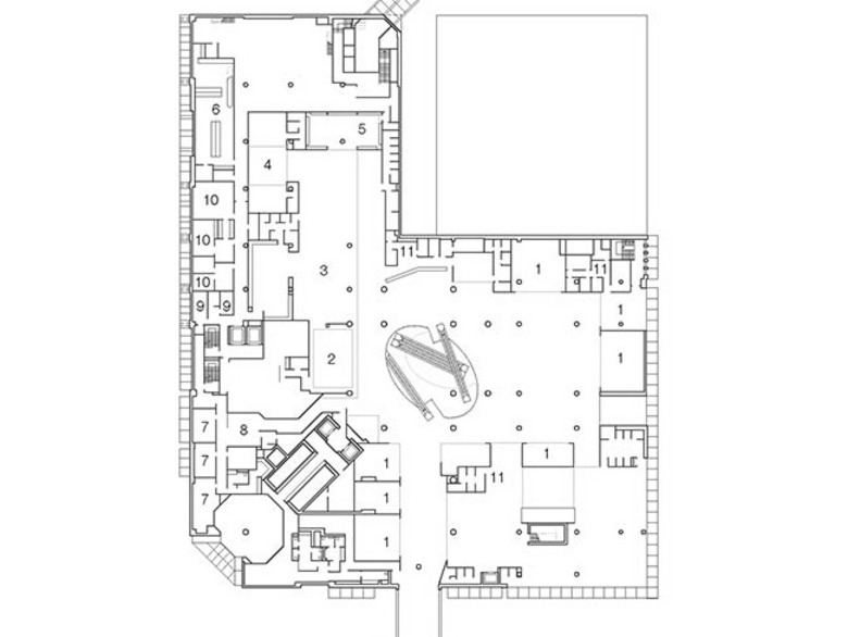
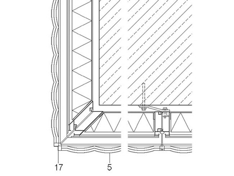
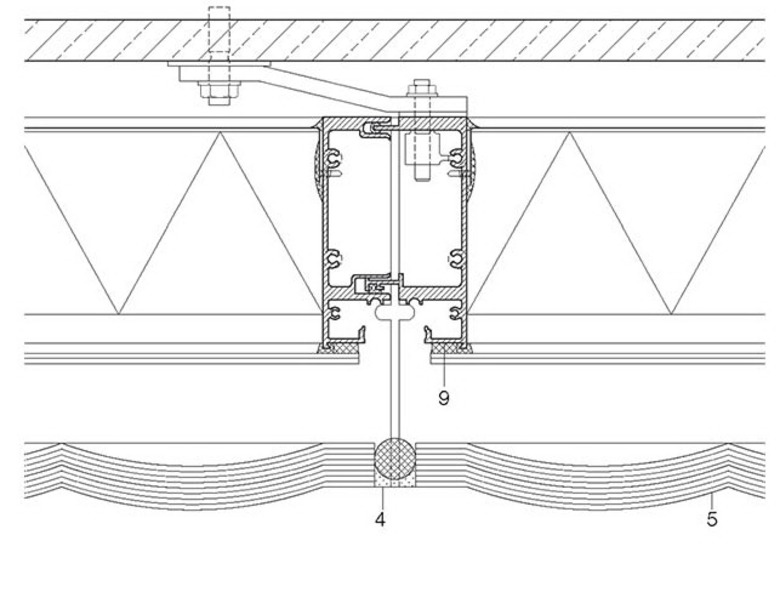
It's easy to get carried away with detailing, but it is important to keep in mind the intended purpose of the particular drawing you are working on. As an example, see the plans below. The 1/8”= 1’ overall buidling plan shows enough line detail to express windows, walls, and other contextual building elements, where as the specifics of detailing, visible in the last plan detail drawing at 6"=1', would not only not be useful in the building plan but would also become a messy blur of lines. This may sound intuitive, however, as a designer moves in the digital realm, where modeling and drawing happen at 'full scale', one can fall into the trap of over-detailing, at the expense of the larger picture.
Construction Drawing Examples: The Phoenix House
Professor Mark Anderson’s firm Anderson Anderson Architecture designed a single-family house that is now under construction near campus. It is an interesting project involving a great deal of cad/cam-prefabricated components, assembled on a difficult site in the Berkeley hills. A variable and systematic level of detail was needed in the construction drawing set in order to effectively coordinate the various trades and methods of fabrication and construction. These drawings emphasize how the Architecture, Engineering, and Construction industries can benefit from explicit representation of the design process rationale in many ways. They also demonstrate how understanding design intent is important for achieving coherent integration of design solutions and transfer of design knowledge.
Below are some of the Architectural drawings that are included in the Construction Drawing set.
Using AutoCAD for 2d Design Documentation
Creating Multiple Viewports in Paper Space
Under the "Layout" Ribbon, use the "Layout Viewports" to add multiple new viewports onto a single page layout. You can do this by drawing a standard rectangular viewport, a polyline shape, or by defining a viewport with a closed polyline that has already been drawn in paperspace.
Creating Annotative Text & Dimensions
Adding Annotative Text
Under the text palette of the "Annotate" ribbon, you can select and modify text styles for a drawing. A useful feature when working with multiple scales in a single drawing is associative text. This will display text at the appropriate height in paperspace based on the scale of a layout. Click the small arrow at the bottom right of the Text palette to bring up the Text Style Manager and check the box for "Annotative" under size. You can also use the “Leader” command to create text annotations with an associated arrowhead leader.
Adding Annotative Dimensions
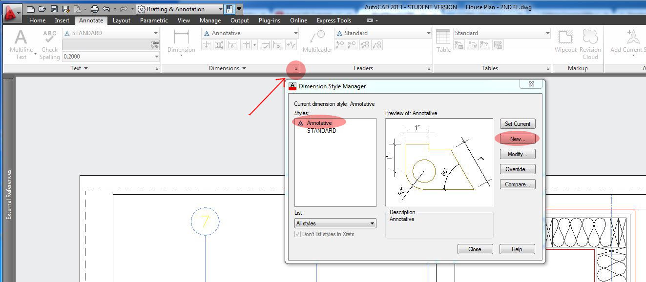
Under the dimension palette of the "Annotate" ribbon, you can select and modify dimension styles for a drawing. Similar to adding text, a useful feature when working with multiple scales in a single drawing are annotative dimensions. This will display dimensions at the appropriate scale in paperspace based on the scale of a layout. Click the small arrow at the bottom right of the Dimension palette to bring up the Dimension Style Manager and either select Annotative dimension style, or select "New" and create a copy of the Standard dimension style. Title this layer "Annotative" and be sure to check the box for "Annotative" in the options dialogue.
Plot Layout Properties in Paperspace
As demonstrated in the example drawings at the beginning of the lecture, it is important not to overload drawings with unnecessary levels of detail if the information will just get messy and confusing at a smaller scale. One way to avoid this is by changing layer visibility in a layout.
Detail Layer Visibility
Open the Layer Property Manager in Paperspace by typing "LAYERPALLETE" into the Command line or from the Palettes tab under the "View" ribbon. From here you can begin to change the visibility of layers in different viewports by activating the model space of the viewport you would like to work with in Paperspace. Under the "VP Freeze" column in the Property Manager, you can turn certain layers on or off depending on how much detail you are looking to display.
Annotation Visibility
It is not always enough to simply make a dimension or text annotative. If a plot layout has viewports at various scales and you only want to display some dimensions or text at a specific scale, you can specify the annotative scales for those specific elements.
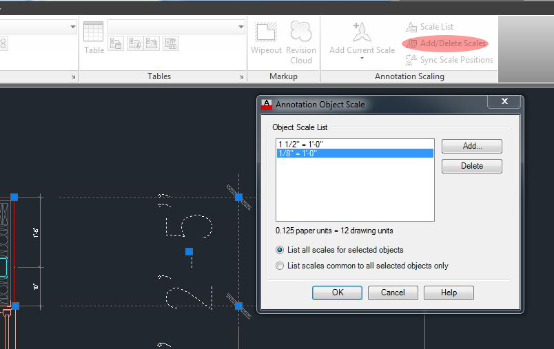
In model space, under the "Annotate" ribbon, click the "Add/Delete Scales" button under the Annotation Scaling palette. Select a line of text or a dimension and press enter or spacebar. A window will appear that will then let you add or delete annotation scales that you would like to have apply to that particular element in paperspace.
Importing DWG Drawings to Illustrator
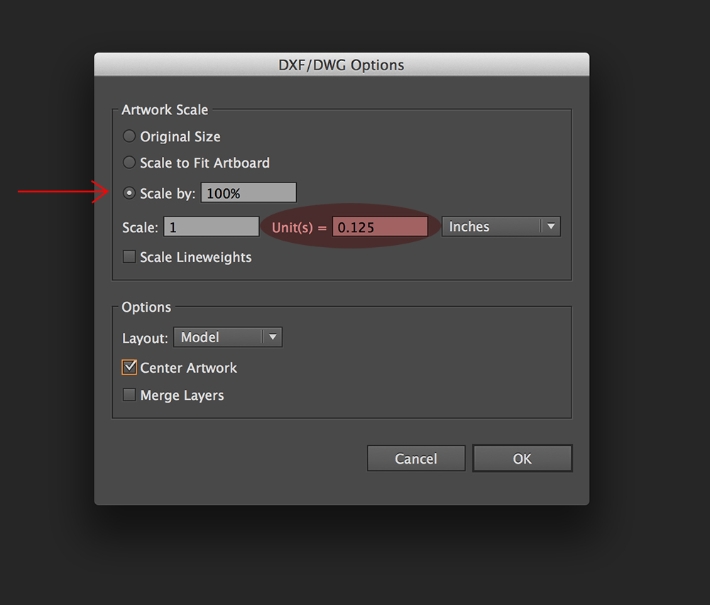
In AutoCAD Part I you learned how to plot a DWG to PDF with appropriate lineweights. It can often be helpful to do more editing, adjusting of lineweights, or post processing to bring a drawing to presentation level after drafting in CAD. You can import your DWG drawing directly into Illustrator to do this while still maintaining source layers.
Workflow: Organizing Detailed 2d Drawings in AutoCAD and Illustrator
This workflow will demonstrate how to create multiple scaled viewports in AutoCAD as a means of showing varied level of detail. As a designer, this is important to know for conveying design intent. The workflow will also show how to add basic annotations and dimensions to your drawing and then import it into Illustrator for post processing.
