| Week 3: AutoCAD (Part I) | |
|---|---|
| Course | Arch 100b |
| Date | 2013/02/08 |
| Learning Objectives | AutoCAD is built for drafting. Using this software will allow you to efficiently manage line types and annotations. You will practice cleaning up a section cut from a Rhino model. In addition to getting familiar with AutoCAD's interface, you will learn how to create and edit geometry, manage your drawings, and how to share information across platforms. These skills will help you take your linework to another level of organization and clarity. AutoCAD is an industry standard software, knowledge of which is a major component to getting hired upon graduation.' |
| Agenda |
|
| Uses Tool(s) | AutoCAD 2012 |
Introduction to AutoCAD
Examples of Working Drawings
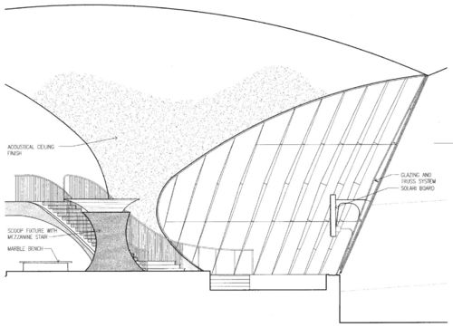
Working drawings used to be simple and beautiful. TWA's Terminal 5 at JFK in New York by Eero Saarinen are a good example of this. The drawing set for this building was about 50 sheets. These drawings were produced by pencils and maylines.
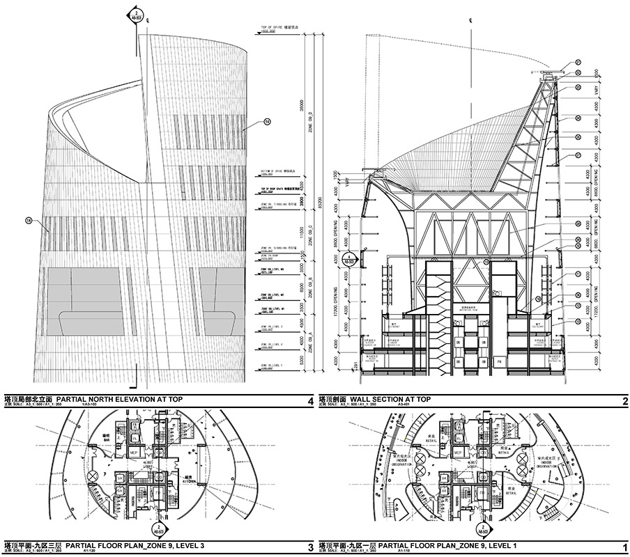
Today's working drawings are far more complex and exhibit much more information. The drawing set for Gensler's Shanghai Tower exceeds 2,000 sheets. Many of them were produce with AutoCAD.
The AutoCAD Interface
The major elements of the interface are called out below. Model space is where one does the drawing, while paper space is where one lays out the plot.
Creating and Modifying Geometry
Creating Geometry
Create geometry by using the "Draw" palette of the ribbon or using keyboard shortcuts.
Modifying Geometry
Modify geometry by using the "Modify" palette of the ribbon or using keyboard shortcuts.
Creating and Assigning Layers
Creating Layers
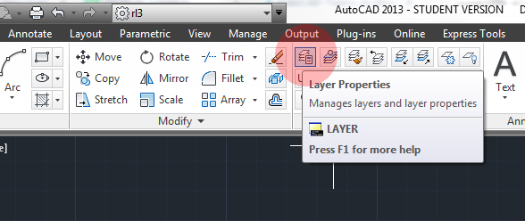
Create a new layer by using the "Layers" palette of the ribbon to launch the Layer Manager.
Launch the Layer Manager by clicking on "Layer Properties"
The Layer Manager shows you all the layers in the file. You can customize this by creating your own layers and assigning properties to that layer here. A new layer is created by clicking on "New Layer".
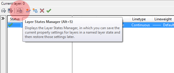
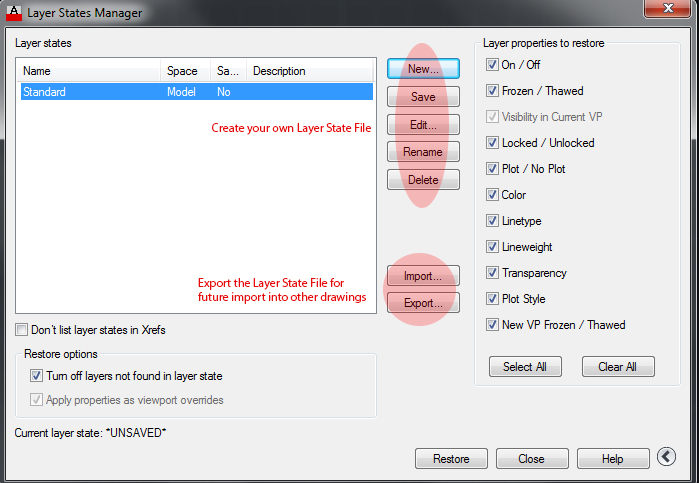
Since you will use mostly the same layers in all your drawings, creating new layers for each individual drawing would be an inefficient use of time. The Layer States Manager allows you to save your layers and their properties, export this and import into a different drawing.
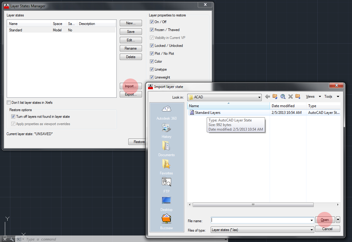
Clicking on "Import" brings up the "Import layer state" dialogue, where you can browse to a previously saved and exported layer state file. This brings all your layers and their properties into the drawing.
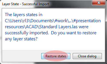
Choose "Restore" in order for the layers to have the original properties that you created.
After importing your layer state file, your layers can be seen in the layer manager as well as in drop-down format on the "Layers" palette on the ribbon. Now you are ready to assign your geometry to layers.
Assigning Layers
Assign a layer to geometry by first selecting the geometry you wish to be on a particular layer, and then selecting the desired layer from the "Layers" palette of the ribbon.
Inserting a Reference Image
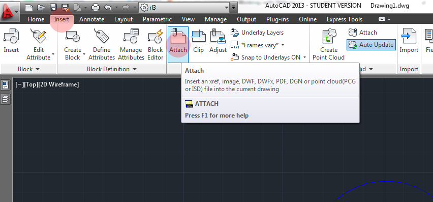
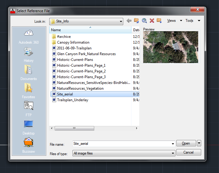
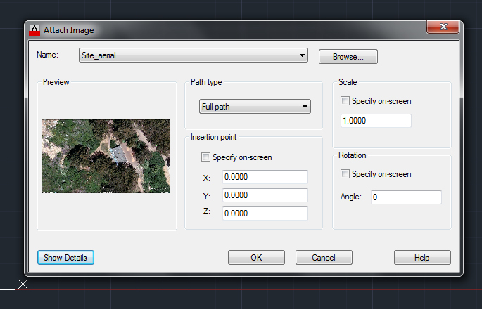
AutoCAD makes it easy to insert a reference image. Click on Insert to bring up the Insert Ribbon, then click on "Attach".
Map to your image file.
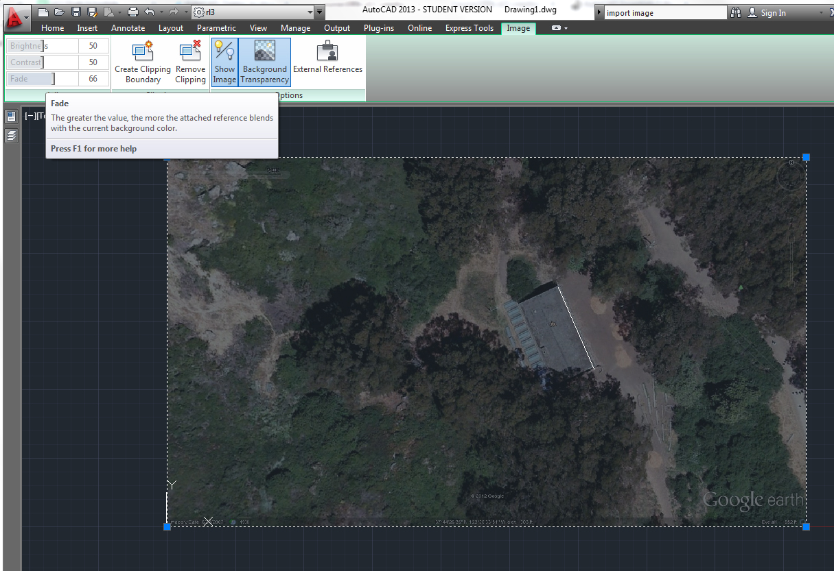
Place in model space.
You can then scale the image, move it, fade it, etc. with the contextual edit tab that appears when the image is selected.
Plotting a Layout
To plot from a layout, go the layout tab. Double click inside the viewport to activate modelspace, then zoom and pan until the geometry you want to print is visible.
Double click out of the viewport and then select it. Set the scale from the drawing properties bar.
Click the print icon to bring up the print dialogue. Select the "DWG to PDF.pc3" printer/plotter driver. Select the appropriate paper size. Plot scale is 1:1 (paper space is real world size, and you have already scaled your drawing by setting the viewport scale). Plot Style Table (Pen Assignments) set to monochrome.ctb. Under Plot Options, make sure "Plot Transparency" is checked if any of your layers are set to a transparency. Set the desired orientation to landscape or portrait.
Click "Apply to Layout" to save these settings and then "Preview" to preview the plot. Right click on the preview to pan and zoom. If things do not look right, select "Exit" to go back to the print dialogue. If things look good, select "Plot". A PDF is then created.
Lab Workflow
Download Files:
Week 3 Materials
Cleaning Up 2D Drawings Extracted from a 3D Model
Lab Exercise
Creating a Wall Section in AutoCAD

