| Week 3 - July 11th - 3D MODELING (CONT.) + DRAWING EXTRACTION | |
|---|---|
| Course | 124a |
| Date | 2014/07/11 |
| Learning Objectives | Moving forward with our 3D models, we will extract 2D drawings from the 3D workspace and move into editing drawings using Adobe Illustrator. Learning how to manage lineweights across platforms as well as preparing files to print, and plotting, will be covered in lecture and workshop. |
| Agenda |
|
| Uses Tool(s) | Illustrator CS5 , Rhinoceros |
Introduction
Having become familiar with using a 3D tool to represent drawings in 2D and creating a 3D model from that information, we will move into extracting 2D linework from our 3D workspace in such a way that one is able to better articulate the conventions of lineweights in drawings. We will be moving between Rhino3D and Adobe Illustrator to achieve these drawings.
3D Modeling - Continued
Blocks
Blocks are a group of linework that can be easily copied and edited throughout a drawing. This can be helpful when drawing furniture, structural details or basic graphics such as doors or windows. These can be imported from another drawing as a block or created as a block within the drawing.
Make 2D
Overview
The Make2D command captures linework in a selected viewport in relation to that viewport's construction plane and projects it as a two-dimensional drawing to the origin (0,0,0) of the X-Y plane.
This is the primary method to make orthographic drawings from a model, allowing one to export resulting linework as an Adobe Illustrator file.
Though Make2D is a versatile and extremely useful command, there are several known issues which are described at length. These issues can be helped or eliminated by following the general preparation instructions provided.
Drawing Extraction
There are a variety of ways to extract 2d line work from your 3d models. Some common ways will be discussed below.
Section
With 3d geometry selected, typing Section will allow you to create an artificial plane anywhere in your viewport simply by clicking any two points. This plane is your cutting plane and the section derived from it will be parallel to this plane. This means that if you wanted to cut your plan, you wouldn't draw your section plane in Top View because that would make a plane that cut through your space from the top down, essentially giving you a section, but you could do it in Front View, where your plane would slice all the way through your model at one consistent height.
Commonly, the Section command is not done ad hoc. You first make section planes that will guide your section planes and will help you split you model to generate additional 2d information that will help fill out your section or plan drawings.
Make sure that when you take your sections, you place them in order in the top view. The top view is the only view that can be exported to Illustrator.
Make 2D
Make 2D will help you get the base lines for elevations as well as site plans. It is also a great way to capture background information that has been 3d modeled.
The Make2D command captures linework in a selected viewport in relation to that viewport's construction plane and projects it as a two-dimensional drawing to the origin (0,0,0) of the X-Y plane.
Though Make2D is a versatile and extremely useful command, but there are several things to remember when working with this tool, mainly involving preparation.
Detail Appropriately
Consider the goal of your digital model. If you desire 1/4" scale drawings of your building, modeling the light-switches may not be efficient and will drastically slow your Make2D efforts. If you require a high degree of detail in your model, ensure that your use of layers allows you to "turn-down" the level of unwanted detail.
Simplify
Join all surfaces into polysurfaces insofar as possible - everywhere surface edges are concurrent, Rhino has to calculate two edges instead of one and see if there are overlaps.
Use the Right Stuff
Make2D does not create 2 D drawings from mesh objects, only surfaces, polysurface, lines, curves, and points.
For a more detail look at Make 2D, visit this tool part page: Make 2D
Laying out 2D Drawings
Aligning Drawings
When you take multiple sections and plans, it's helpful to line them up for registration. Often, you'll be able to carry dimensions and construction lines through multiple drawings. This is a time saver as well as a good way to begin thinking about how you might line up your final drawings. Ground planes are always a good anchor for lining up drawings, but any shared line can work.
Construction Lines and Section Lines
With proper alignment, your drawings can begin to speak to each other through construction lines, which will connect shared edges across the drawings. Any line or aspect from a drawing can be called out through a construction line that leads to other drawings and so on and so forth.
Your sections should always be referenced in either a plan or a site plan, which includes the labeling of your sections before you export. If you have a lot of drawings, they can get confusing without a labeling system. Commonly section lines are dashed and lighter than most other lines.
2D Details and their 3D consequences
Often you'll cut a section and start making it look nice by adding thicknesses, trimming unnecessary lines, and doing general clean up, but you'll also start adding details relating to your tectonic system, building assemblies and overall methods of construction. When you make a detail in 2D, moving back to 3d to incorporate the detail can help you continue to think in 3d space and can allow for increasing rendering detail.
Exporting to Illustrator
Once you have your section linework in place, select your drawing(s) and click "export selected" in the File menu bar. You can chose from a variety of options, but for drawings, we will chose either .dwg (Autocad Drawing File) or .ai (Adobe Illustrator). Both are editable in Illustrator, but the .ai file requires that you change size when you export. If your drawing was made specifically for a certain size, exporting directly to that size make sense, and the .ai file type would be best, but if you would like the ability to select the scale of the file when you open it in Illustrator, the .dwg will allow you to do that.
Moving back to Rhino after having made adjustments in Illustrator can be tricky. The layers from Illustrator will not be retained if you open it in Rhino, but the colors will be. This means, you could use "SelColor" in Rhino to make new layers based on their color, but if you have a line drawings in black with different weights as the only difference, you won't be able to distinguish the different layers any longer. In general, don't plan on going back and forth between Illustrator and Rhino. The changes you make to your drawings should be happening in Rhino, where Illustrator is just used for realizing the line weights and visual graphics.
Common Problems
"My drawing doesn't show up in Illustrator or is way off the artboard."
If this happens, try moving your geometry to the origin and export again. Rhino doesn't intuitively assume that the center of your selected area is supposed to be the center of the exported area.
Additional References
How to create a clean drawing from a 3d model in Rhino
Illustrator Basics
Adobe Illustrator CS6 is a vector graphics editor and has a very specific set of functions that make it optimal for creating and editing vector-based (or line-based) drawings. Vector editors are often better for page layout, typography, logos, sharp-edged artistic illustrations (e.g. cartoons, clip art, complex geometric patterns), technical illustrations, diagramming and flowcharting. In the practice of architecture, we typically use it to create presentation-ready orthographic drawings and technical or detailed diagrams.
In contrast to Photoshop, which is intended to edit and create rasterized (pixel-based) images based in bitmap format, Illustrator works with vectors - lines defined by mathematical equations and points. Photoshop and Illustrator have begun to overlap in some of their abilities, but it's important to remember that they are primarily intended to be used with their respective formats. Don't try to do finely detailed photo manipulation in Illustrator, and don't try to edit your architectural drawings in Photoshop!
Vector vs. Raster
To understand when it's best to use Illustrator, you need to get a handle on vector and raster images. A rasterized image is made up of pixels and does not scale up without decreasing quality, while a vector image contains is merely point information connected by specific curve angles and can be scaled up without any loss of quality.
Vector: Left, Raster: Right

RGB vs. CMYK
Digital images are conventionally displayed in RGB (Red, Green, Blue), as these primary colors represent the purest way to translate color information, while printers translate the RGB values into CMYK (Cyan, Magenta, Yellow, Key-black), using a secondary color spectrum to represent color. This simple distinction means things look different when you print them from what they appeared to be on your screen. Depending upon your final output and media, you will need to properly determine your color space.

Layers
The various elements in your illustration start with a base layer that is added to with subsequent, additive layers. By working with your changes as layers, you will be able to turn on and turn off elements on the canvas and allow for a versatile working image, not an unchangeable singular image. Using the layers panel is an essential tool for Illustrator at all levels of expertise.
Important Tools in Illustrator
- Selection Tool (Black Arrow, V)
- The most essential tool to Illustrator, allowing you to select and move objects.
- Direct Selection Tool (White Arrow, A)
- Select singular objects within a group (without entering into isolation mode) or to directly select anchor points.
- Pen Tool (Fountain Pen, P)
- Create point-to-point straight lines, complex vector lines, or vector shapes point by point, with direct manipulation of each anchor point. Also tied to this tool are the following: Add Anchor Point, + , Delete Anchor Point, - , and Convert Anchor Point, Shift + C .
- Line Segment Tool (Line Icon, \)
- Draw a single line segment from one point to another, without ability to directly manipulate anchor points while drawing.
- Type Tool (Type Cursor, T)
- Place lines or blocks of text, with ability to edit font, size, indentation, tracking, leading, etc. Click for text line, Click and drag for text block.
- Pathfinder tools
- Similar to Boolean operations modeling program, the Pathfinder tools allow you to unite, intersect, exclude, etc. vector shapes.
- Create Clipping Mask
- A clipping mask is an object whose shape masks other artwork so that only areas that lie within the shape are visible—in effect, clipping the artwork to the shape of the mask. You can make a clipping set from a selection of two or more objects or from all objects in a group or layer.
- Swatches
- Swatches are named colors, tints, gradients, and patterns. Swatches can be either rasterized images or vector-based artwork and can be tiled to create an endless pattern to fill a vector shape.
- Color
- Fill color and stroke color can be changed in the toolbar or by selecting a swatch from the Swatch panel. Colors are built in one of the following ways: process (Pantone or another color system, typically for print), CMYK (print) color space; or RGB (web/digital) color space.
Here are also some helpful tool panels to help you get acquainted with the Illustrator user interface.
-
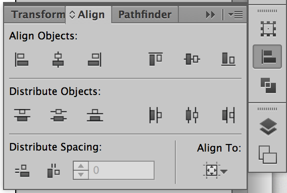
Align objects to the artboard or other objects
-
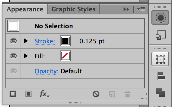
Change the appearance of objects using effects
-
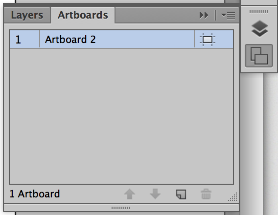
Add, remove, or edit artboards
-
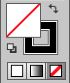
Change the color of an object's fill or stroke
-
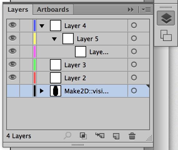
Add, remove, and edit layers, create sub-layers, and view layer contents
-

Boolean-like operations for vectors
-
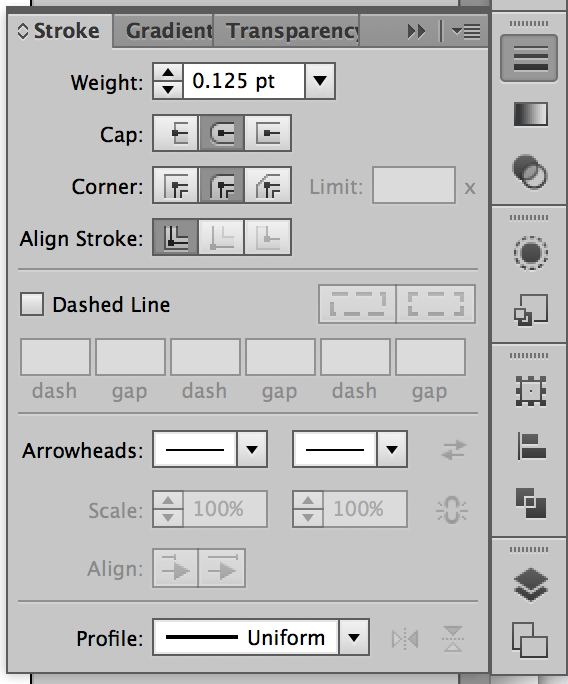
Change stroke properties
-
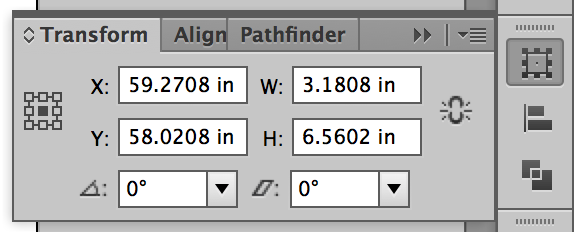
X,Y coordinates, WxH properties, Rotation, and Shear


Demonstration
Our in-class demonstration will give a technical overview of how Illustrator is used in architectural practice.
Sorting out Imported Linework
When exporting linework out of CAD programs, and especially when taking drawings created by the Make2d command in Rhino, it's important to clean up any lines that may have become distorted. Though much of distorted linework can be corrected in the original CAD program, Illustrator has many tools to help in the process too. Using the Pen tool will allow you to draw complex curves or reconnect broken lines. The Direct Selection tool will allow you to select points and reconnect them to other points with the Join command.
Once you've cleaned up your drawing, you'll also be able to change the lineweights by changing the stroke weight in the stroke panel. If you thought ahead and organized you CAD drawing into layers by lineweight, you'll be able to easily select an entire layer's contents to change it's stroke weight. If not, you can also do this manually. You can also turn solid lines into dashed lines, and change the dash pattern and stroke cap.
Notation of Existing Drawings
You can also add text to your drawings to notate your plans. The Text tool has a few different modes.
By clicking once with the Text tool, you'll be able to create a free line of text that is unbounded and will only begin another line by hitting the Return key. This is a great way to notate drawings for concise labels.
By clicking and dragging with the Text tool, you'll create a text box that will keep all text within its boundary. This is particularly helpful with large amounts of text, as you can create multiple text boxes and flow text from one box to the next.
Finally, you can also click on a line with the Text tool to type along that stroke. The stroke can be simple or complex, but the text will follow it's path. This is particularly helpful when flexibility with type is needed, such as in diagrams.
Layered Drawings
The ability to draw in layers is key to using Illustrator. It will allow you to quickly alter your drawings in a detailed way without disrupting the other parts of your illustration. By separating your drawing out into layers, you can quickly select all of the layer's contents to change the attributes en masse. You can also add more layers to your drawing for poche or color while keeping these separate from the base linework.
Poche
Poche is the solid of a drawing to the space's void, and can aid in reading the relationship of inside to outside. By using the Pen tool or the Polygon tools you can create the vectors necessary to fill in your poche on a separate layer, then place it all the way to the bottom of the layers so that the lines from the drawing read clearly.
Hatching, Texture, & Materiality Through Swatches
Similar to AutoCAD hatches, you can create pattern swatches to add as an object's fill. Many swatches already exist in Illustrator for you to use by clicking the menu button on the Swatches panel and clicking on Open Swatch Library.
Clipping Masks
We've already discussed how clipping masks are used, but we should also understand the concept of a clipping mask with regard to layering. A clipping mask uses a closed vector to clip (or crop) an image or other set of vectors below. This is achieved by placing a vector on top of the desired objects (you can use the Bring to Front command to ensure the vector is above all the objects) and right-clicking on the screen and clicking Make Clipping Mask.
Once the mask is created, you can double click on the mask to enter into Isolation Mode and edit the contents of the mask or the vector of the mask itself. You can also edit the mask vector with the Pen tool or the Direct Selection tool. In the Layers panel, you'll be able to find the clipping mask has essentially created a new layer with all of the clipped objects inside that layer. Dragging objects into or out of this sub-layer will add to or remove objects from the clipping mask.
See the workflow at the bottom of this page for a more in-depth description of how to use clipping masks.
Blend Tool
Use the blend tool to achieve gradual transitions from one vector shape to another while maintaining it as a dynamic object. In the Blend tool dialog, you can change the mode of blending and distances between steps or the amount of steps from the first shape to the end shape.
Board Layout
Though Illustrator is not the most appropriate Adobe Creative Suite program for combining text and images into a presentation format (InDesign is more suited to handle that task), it can still be helpful for quickly mocking up boards or creating less formal presentation boards.
Artboards
In the Artboards panel, or by clicking on the Artboard tool, you can alter the size and orientation of your boards or create new boards. While editing, you can alter the exact size of the boards by changing the dimensions in the transform panel at the top of the window.
Placing Images
You can place images into your Illustrator file by going to File>Place... and choosing an image file. After choosing the desired image there are a few options at the bottom of the dialog, the most important being the Link checkbox and the Replace checkbox.
Linking a file will place an instance of the image in the file, but will not embed the image - any changes made to the original placed file will be read back in to the Illustrator file. If you do not click this checkbox, the image will be embedded and no changes to the original file will be read. Linking images minimizes file size and keeps Illustrator running smoothly.
Replacing a file will place the new image into any placeholder that was selected before choosing File>Place....
Additional Resources
- Adobe Illustrator CS6 Help
- Adobe's Help site for Illustrator.
- Method & Craft
- Advanced, specific techniques for Illustrator, Photoshop, Dreamweaver, and other software. Oriented towards graphic designers, but still of use.
- Drawing Architecture tumblr
- Collection of beautiful drawings by professionals and students for inspiration on technique and style in representation.
- Graphic Addiction tumblr
- Collection of student project representations. More rendering heavy, but still includes great line drawings.