| Workshop 1c | |
|---|---|
| Course | Arch 200c |
| Date | 2013/09/17 |
| Learning Objectives | This workshop covers the conventions of scaled architectural drawings. In it, we'll be discussing the more technical aspects of architectural drawing, including drawing to scale, standard architectural notation for section cuts, program and floor labels, graphic scales and north arrows. We'll also discuss how to read topographic lines, how to place plan and section cut lines, when it's okay to "lie" in a drawing (when we can deviate from strict graphic projection techniques), how to depict stairs, ramps, elevators and mechanical spaces, and how to choose the appropriate level of detail for walls, roofs, and floors in section and elevation. |
| Agenda |
|
| Uses Tool(s) | Drafting Board |
This session will be led by Rudy Letsche.
Workshop 1c - Architectural Drawing at Scale
Use this file to follow along:
Drawing Standards
Architectural drawings are drawn to scale so that relative sizes are correctly represented. The scale is chosen both to ensure the extents of the building will fit on the chosen sheet size as well as representing the required amount of detail. At a scale of 1/8" = 1' (1:96 or metric equivalent 1:100), walls are shown only as simple outlines relating to the wall's overall thickness. At a larger scale such as 1/2" = 1' (1:24 or metric equivalent 1:20), layers of materials that make up the wall construction are depicted. Construction details are drawn to an even larger scale with even more detail, showing structural or aesthetic connections, and in some cases full scale (1:1).
Scale drawings enable dimensions to be measured directly off of the page using an architect's scale or a given graphic scale. On a 1/8" = 1' scale drawing, the 1/8th divisions on the ruler can be read off as feet. Still, because of reproduction errors, it's important to remember to include figured dimensions on the drawings that would be used for construction.
Graphic Projection at Scale in Architecture
The images below will help you to understand the concept of orthographic drawings in the architectural context with basic examples of each drawing type. You can also review our discussion of the basic architectural drawing types or refer to our overview .
-

Orthographic Projection Concept Illustrated
-

Section Concept
-

Example of Elevation


Architectural Plans
An architectural plan is a sectional drawing wherein the cut plane is positioned parallel with the ground. In most plans, the cut plane lies at a standard distance (typically 4') above the ground (a "ground plan") or above an occupiable floor (a "floor plan"). While following all the conventions of a typically architectural plan, a "site plan" isn't technically a sectional drawing at all, as the projection plane does not intersect any objects.
Plans are the most widely used graphic device in architecture. They can reveal the interrelation between the interior spaces of a design, how an occupant is able to navigate these spaces, and the relationship between a building and its surrounding context.
Architectural Sections
An architectural section is a sectional drawing wherein the projection plane is positioned intersecting the objects or space of interest, and is not parallel with the plane of the ground. Sections are most often perpendicular with the ground (vertical), but this is not a defining characteristic.
Sections are extraordinarily useful in architectural design, and can reveal the interior composition of wall systems, the interrelation of adjacent spaces, and the relationship between a building and its surrounding context.
Architectural Elevations
At first blush, an architectural elevation does not seem like a sectional drawing at all, as the projection plane does not intersect any objects of interest. Seen another way, we may define an elevation as an architectural section in which the projection plane is positioned near to, but not intersecting the objects or space of interest. Section or non-section: in either case, architectural elevations are useful for describing the exterior composition of a building, and the way in which it sits on a site or in relation to neighboring buildings.
An elevation is essentially a view of a building seen from one side as a flat representation of one façade and is the most common view used to show the external appearance of a building. Each elevation is labelled in relation to the compass direction it faces; for example, the north elevation of a building is the side that most closely faces north. Since many buildings are not simply rectangular in plan, a typical elevation may show all the parts of the building that are seen from a particular direction.
Oblique & Axonometric Projection
To show an implied 3rd dimension in 2D drawings in an architectural drawing, oblique and axonometric projection are used.
Scales and Systems of Measure
Architectural drawings are drawn to scale so that relative sizes are correctly represented, and so that the drawing may be used for the extraction of dimensional information. The scale of a drawing is chosen both to ensure the extents of the building will fit on the chosen sheet size as well as representing the required amount of detail given the type of drawing at hand.
An instrument called a scale is used for this purpose.
Level of Detail
Based on the scale you used to represent your project, different levels of detail will be required to allow the drawing to read as an architectural space.
-

Wall & Window Detailing
-
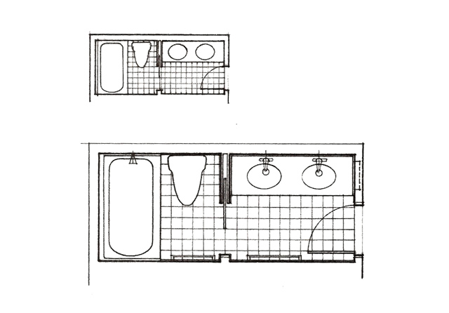
Fixtures Detailing
-

Xeros House, Upper Level Plan
-

Burton Barr Library
-
Level of Detail in Elevation


Orthographic Standards Review
Conventions of Drawing Architectural Space
Line Weights, Styles, and Types
Look at our tool part on line weights to review the conventions and the importance of line quality to drawing legibility, or refer to the images below.
-

Pencil Lead Weights
-

Line Types and Styles
-

Importance of Lineweights in Plan


Architectural Elements

Architectural Notation & Graphic Symbols

In-Class Exercise
Since you've just presented the first iteration of your orthographic drawings required for studio, and have your second iteration due tomorrow, this in-class exercise will seek to apply some of what we've discussed today to your studio design drawings.
- Pick one of your section drawings. Rework the poché to show different design intents. Think about what connects to what. Do two versions. Work quickly.
- Pick one of your elevations. Depict different surface designs - think of many small parts connected or few large parts connected. Think of thick connections and thin or fine connections. Do these parts connect on the same plane, or does one material come out more than another? How would you represent this using only lines?
Reminders
We'll have a studio redline pinup during our next class session (this Thursday). Please have a draft version of all required drawings pinned up in room 901 by the start of class.
We will be discussing our first set of readings next Thursday. Everyone is expected to have read two readings out of those listed on here . You should look ahead to see if you are leading the discussion, if so, summaries are due by midnight on Tuesday!