| Week 1 - Double Negative 1 | |
|---|---|
| Course | Arch 100A |
| Date | 2013/02/01 |
| Learning Objectives | This session will provide an overview of the goals and expectations of the digital course. An introduction to Rhino will emphasize surface modeling using solid modeling tools, basic surface commands and boolean operations. |
| Agenda |
|
| Uses Tool(s) | Rhinoceros |
Introduction to Rhino
In this course, Rhino 4.0 will be the primary modeling program that we will use to create orthographic linework, architectural diagrams and perspective drawings.
As part of the Wiki, feel free to browse the Tools page on Rhino to find more information on the entities, interfaces and methods specific to the program. We will be referring to these often as they come up in the course.
Rhino is unique in that it creates NURBS based surfaces , in contrast to Meshes. NURBS allow for more complex geometries to be calculated with much less information, according to control points that are often not touching the surface itself.
Rhino Basics
-
Options
- This is where you can edit the colors, units, Rhino render and viewport settings.
-
Object Properties
- This is where you can find information on the objects you are selecting or your viewport properties.
-
Layers
- Layers are essential for file organization. Get comfortable using layers for different elements and labeling them properly.
-
Toolbars
- Right click on the gray headline if you are ever missing certain toolbars or to to Tools > Toolbar Layout... to restore defaults.
-
Aliases
- Change, update or import different shortcuts and commands
Working in 3d
- 3d Coordinate System
-
Object Snaps
- Using snaps is key for maintaining precision.
- Be careful that you don't have too many OSnaps on because then you might snap to the wrong one.
-
Viewports
- Being precise when modeling in 3d involve using the different viewports as much as possible.
-
Editing Tools
- Move, Copy, Rotate, Trim, Extend
- Rotate3d, ExtendSrf, FilletSrf
- POn (Points On), POff (Points Off)
- Scale, Scale1d, Scale2d
Solid Modeling
Solid modeling is based on a variety rational surfaces that create perfect geometry based on an equation. These objects are usually closed polysurfaces made up of one or more surfaces.- Some forms have additional input options. This is show by the little triangle in the corner of the box
- When placing these forms, you can either type in coordinates or precise lengths in the command line, or click in the viewport spaces.
Surface Commands
Many of the surface commands require inputs of existing linework. There are various ways of modeling surfaces, which may have to do with precision, smoothness, water-tightness, or something else. All of these commands can be found under the Surface option in the toolbar.
- Surfaces can be joined to become a closed polysurface ("solid")
- TUDelft offers examples of most of the surface commands on their wiki page here .
Surfaces
- Plane, Plane (Vertical), PlanarSrf, PlaneThroughPt, CutPlane
- These are essential when you need to create a planar surface - which we often need to represent something physical such as a wall or a piece of chipboard. These also require our linework to be planar - which might require Make2d or Project to Surface.
Extruded Surfaces
- ExtrudeCrv, ExtrudeCrvAlongCrv, ExtrudeCrvTapered, ExtrudeCrvPoint, Ribbon, Fin
- When working from existing linework, such as a plan and section, these extruded tools are very easy to use.
Non-Planar Surfaces
- Non-Planr Surfaces
- SrfPt, EdgeSrf, Loft, Revolve, RailRevolve, Sweep1, Sweep2
- When simple extrusions won't work, these tools allow more control as to how the curvature is extruded along the linework. These also come with their own tool menu to allow for more precision or smoothness.
- Example Files
Boolean Operations
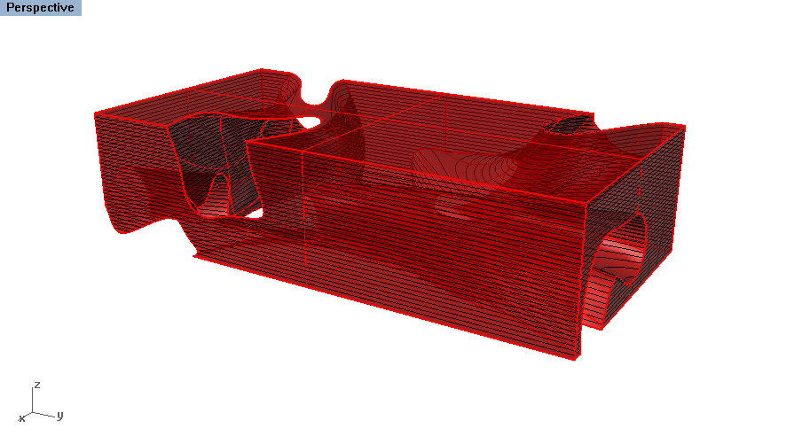
Boolean operations are editing tools specific to solid objects. These can be great time savers especially for the double negative. Type Booelan2Objects and select two objects to go through the different options.
- Union
- Joins the geometry into one polysurface by trimming out the interior intersecting spaces
- Intersection
- Keeps the shared parts of the polysurfaces
- Difference
- Removes one set of polysurfaces from another
Having problems with your Boolean operations? Sometimes this has to do with out the original geometry was constructed. See this McNeel page for more assistance.
Exercise: Modeling the Double Negative
Workflow: Three Methods for Making a Double Negative
Exercise:
Practicing the Three Modeling Methods
This exercise must be submitted to your bSpace dropbox by the end of class. Files should be titled as follows: "Lastname_Firstname_Exercise1.3dm"
The emphasis on this exercise is to show that you are able to work in 3d space and have practiced using different commands to create surface geometry. Do not obsess about the final forms created here - instead spend that time focusing on your double negative model for studio.
Tools for Building Physical Models
Different forms and projects will cater to different physical modeling strategies, to be discussed further in studio. Below are a variety of tools helpful for creating physical models from an existing digital model:
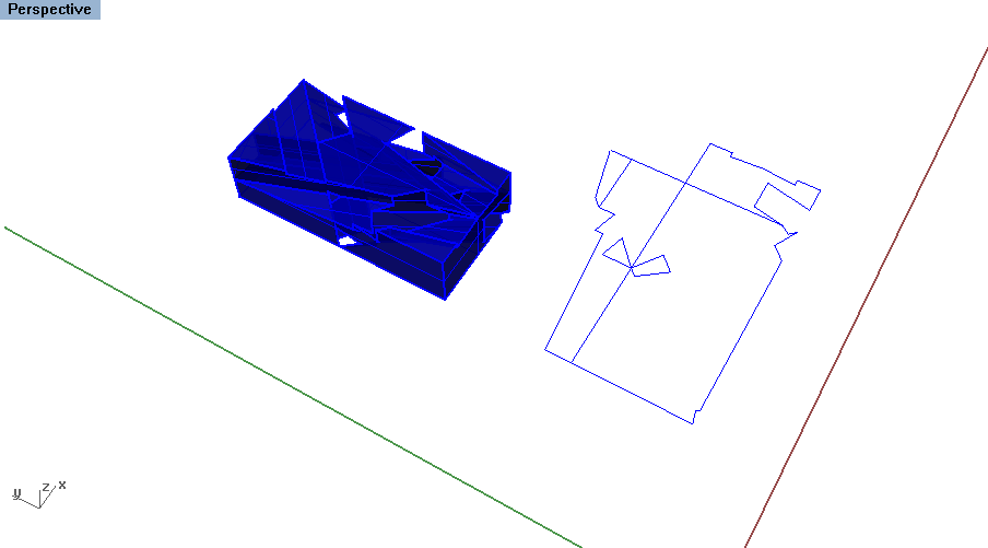
- UnrollSrf or Smash
- This takes a polysurface and unrolls on the XY place to create a origami template for creating the model. While it sounds ideal, the more complex the geometry becomes, the unrolled surfaces have a tendance to fold back upon itself. To make things easier, Explode the original Polysurface and Join different segments together to UnrollSrf . Note: the resulting geometry does not account for thickness.
- Smash is a very similar command made for objects that have some slight curvature inherent in them (and therefor not typical for an unrolled surface). Test this command if UnrollSrf does not work.
- Contour
- Laminated models are a create tool for creating curved geometry. Use the Contour command to set up serial sections that occur alongside an object according to set distance.


