| Week 8 - Physical Modeling from Digital Models | |
|---|---|
| Course | Arch 100a |
| Date | 2012/10/19 |
| Learning Objectives | Overview of common model making strategies and materials including example models. Emphasis on precise construction methods (good tools + techniques, good materials to use, and additional tools available in Wurster) and conceptual intent (model strategies informed by overall concept rather than standard chipboard models). Discussion of how Rhino and other plugins can assist production especially for laser-cutting, CNC-ing and 3d printing. |
| Agenda |
|
| Uses Tool(s) | Rhinoceros |
Recap from Last Week: Plans + Sections
There still seems to be a bit of confusion with several aspects of plan and section drawings.
- Proper line weights
- Hidden lines (dashed lines for things beyond)
- Depth of drawings
- Incorporation of program
- Use of texture for paving and landscape
Please see this page for a recap, and take a look at the example images below. These images are presentation drawings taken from a variety of architects.
Introduction to Physical Modeling
Design Intent
In all methods of architectural representation, it is important to communicate not just the "facts" of the design, but also the intention behind the design. This holds true for physical models, and especially for site models in particular. It would be a missed opportunity to consider a site model as just a 1:1 representation of your design's surrounding context. Instead, the site model is a way of reinforcing and extending the logic behind your design. The way you choose to construct a site model should therefore be closely related to the concept and methodology of your design. This will help your design relate better to the surrounding context (both visually and conceptually) by establishing some sort of important relationship to the site.
Preparing the Digital Model
Before attempting to prepare any cut files, several steps must be taken to ensure that the digital model is ready.
- All polysurfaces must be closed . To check if a surface is closed, click Details in the Properties panel, or simply type What in the command line. The resulting dialog box will tell you if the polysurface is open or closed.
- If the polysurface is open, use the ShowEdges command to identify any naked edges . A naked edge exists when the edge of one surface does not cleanly meet another surface edge. Essentially, a naked edge is a hole that prevent a polysurface from being watertight. After identifying any naked edges, use appropriate surface modeling commands (i.e. JoinEdge , SrfPt , etc) to edit those highlighted edges until they meet cleanly and the polysurface is closed.
- SCALE : It can often be useful to scale the digital model to the actual scale of the intended physical model. This makes it easier to think in terms of material thickness. To do this, use Save As to save your Rhino model as a separate file that will only be used for the production of the physical model. Then, scale the entire digital model, making sure that no layers are locked and that no objects are hidden. For today's exercise, the scale of the physical model will be 1/8" = 1'-0".
Preparing the Ground Surface
One of the most important steps is preparing the ground surface so that it is a closed polysurface , instead of a floating plane. This essentially means we must "box out" the ground surface by creating side walls and a bottom surface so that it becomes a solid object. Additionally, we must fill in all of the holes where the building footprints are and join everything together into a closed polysurface.
For today's workflow, we have already completed these steps, since they can be rather time-consuming. However, you will have to complete these steps for your own site model in the future, so check out this workflow to follow along.
3 Methods of Physical Modeling
Today in section, we will cover three main methods of building physical site models, one of which you are probably already familiar with (laminating). The other two (unfolding and surface modeling) will probably be extremely useful for the group site model that you are building in studio.
Laminating
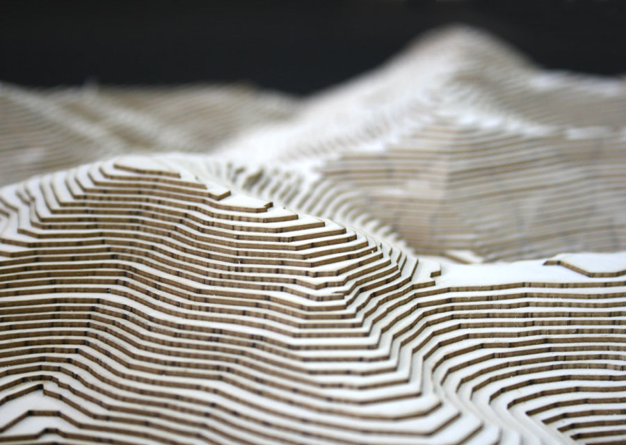
Lamination is a method of physical modeling that involves stacking pieces of material on top of each other with no space between them.
Orientation
The most important decision to make with lamination is the orientation. For example, I could model a rectangular building by stacking horizontal pieces on top of each other, but I could also model the same building by gluing vertical pieces together. The decision about orientation can help reinforce some of your design ideas. For example, should the lamination of the buildings be oriented the same way as the lamination of the ground surface? Why or why not?
Contouring
The process of lamination involves using the Contour command to create sections through the polysurface. Material thickness is very important, since this determines the spacing between each contour. For example, if you are using 1/8" chipboard to build your model, then your contours should be spaced 1/8" apart. Make sure to measure your material very carefully if you choose this method.
Material
The choice of material is also important because of how the revealed edges will look. For example, if the model is made of corrugated cardboard, then the corrugation will be revealed on the outside of the model. The sides of the model will therefore look very different than the top and bottom faces of the model. The corrugation will also look different depending on how you cut the cardboard (i.e. parallel to the corrugation vs. perpendicular or diagonal). How can you use this factor to reinforce your conceptual ideas?
Unfolding
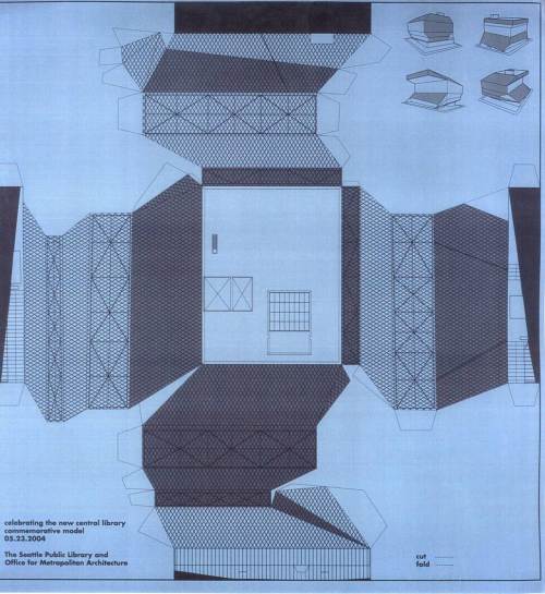
Unfolding a polysurface enables you to flatten all of the individual surfaces onto a single plane, while still maintaining some of the connections between them. It's the architectural equivalent of a bear skin rug--taking all of the bear's skin and laying it flat on the floor, while keeping it intact as a single piece. The benefit of doing this for physical models is that the surface can then be cut out of a single piece of material and folded back into a closed polysurface.
Process
This method uses the UnrollSrf command. In the command line, there are several options to alter the way this command is performed. The Explode option is probably the most important. This determines whether the individual surfaces are separated and lined up next to each other, versus keeping all surfaces intact as a single piece. For the unfolding process, we do not want to explode. The other important option is Labels . If selected, this will label each surface edge so you can understand which edges were originally joined together. This is a useful option when unrolling very complicated polysurfaces, but is generally not necessary when working with simpler forms.
Advantages
This technique minimizes the number of glued surface edges, which tend to be the weakest and sloppiest parts of a model. Instead, it replaces many of the connections between surfaces with a fold, which is cleaner and more precise.
Disadvantages
The UnrollSrf command has several drawbacks, most notably the fact that it does not work on doubly curved surfaces. While it works okay on single-curved surfaces, the command will not work if the polysurface is curving in more than one plane. Furthermore, if the polysurface is incredibly complicated and has a lot of individual surfaces that make it up, this command sometimes is unable to unroll the polysurface without having individual surfaces overlap each other. In these instances, it can be useful to explode the polysurface, join portions of the individual surfaces back together, and unroll each portion individually. This is a good method of troubleshooting the command's shortcomings.
Material
When using the UnrollSrf command, it's important to consider the thickness of the physical material you are modeling with. This technique as described above is for folding paper models, where the material thickness is essentially negligible. For thicker materials, surfaces will need to be trimmed in order to account for the thickness of the adjacent material. This is one reason why it's helpful to have the digital model scaled down to the actual size of the physical model.
Surface Modeling
This Rhino file walks through the basics of how surface modeling works.
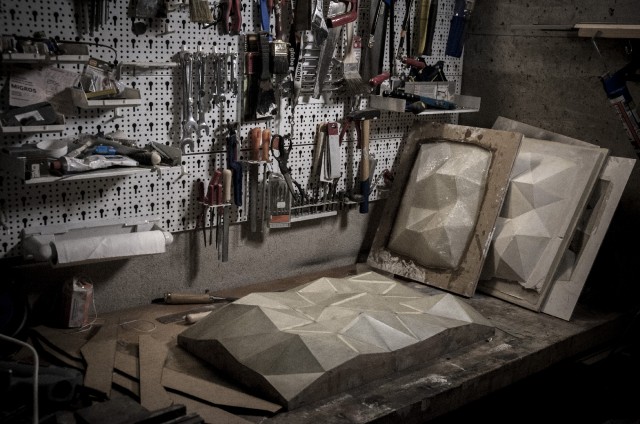
The Surface Modeling technique allows you to restructure the geometry of complicated surfaces. It is essentially the process of tessellation--taking a curved surface, and rebuilding it with a series of small triangles. This is a good way of approximating a curved surface, though it will not be exact. However, for physical modeling purposes, this is often the best way to tackle complex, curving surfaces.
Rebuild
This method starts by using the Rebuild command. The rebuild command allows you to change the number of Isocurves that Rhino uses to calculate a surface's geometry. Remember that isocurves are the secondary gridlines that appear on all surfaces in Rhino. To make sure isocurves are turned on, check the Properties panel and make sure that the Isocurves Visible option is checked when the surface is selected. Then, change the number of isocurves in the X and Y directions, and check the Preview button to make sure it looks how you intend. It is common to have a different number of X and Y isocurves, depending on the surface's geometry.
Triangulate Surfaces
The next command is to ExtractWireframe . This will turn the isocurves into actual curves in Rhino. (An alternative to the "Rebuild-Extract Wireframe" sequence would be to use the "Contour" command in both directions). You can then use the SrfPt command to create 2 triangular surfaces within each "box" of the gridlines, using the intersection points of the contours as the endpoints.
Preparing Templates: Common Problems
No matter which method is used to model the Rhino geometry, it's important to set up precise templates for cutting the material. These templates can used in 1 of 2 ways:
- The cut file can be used to laser cut material
- The cut file can be imported to Illustrator, printed on paper, and physically fixed to the material to be manually cut by hand
Either way, the cutting templates are basically the same. There are some key points to consider:
- It's important for all of the lines to be in the same vertical plane. Often times, when these modeling methods are performed, the linework may end up being in different vertical planes. An easy way of fixing this is to perform the Make2D command to ensure that all lines are on the same plane. This is true for all 3 methods.
- It's important for all of the linework to be joined and closed so that there are not any gaps, because this leads to imprecision. This is especially true for the laser cutter.
- Efficiency of material is important. For this reason, the objects that are being cut out should be placed very close together (and can even share edges, if possible). Try to limit the amount of "wasted" material in between objects. If you can arrange objects so that they share edges, this benefits you in two ways: 1, it wastes the least amount of material and 2, it reduces the number of cuts you have to make.
- You should also arrange linework by the sheet size of the material you are cutting. For example, if you are manually cutting pieces out of a 24" x 36" piece of chipboard, you should draw a box in Rhino that is 24" x 36" for reference. Offset this box 1/4" inside to leave room for clean edges (and to make sure no objects fall off the page). Then, arrange your linework inside of this box.
- If the cut files become very complicated, it's helpful to label the individual pieces (using the Text command) so that you know how to re-assemble them once they are cut out.
Other Methods
- 123 Make by Autodesk
- This website offers a plugin that automatically creates file templates for both laminated and waffle models. Works best for simple forms.
- Waffle Method Workflow
- Written by Johanna Kanerud, Rhino file with instructions here . Separate workflow will be posted soon.
Workflow
For the workflow today, you must pick ONE of the three physical modeling methods that were shown in lecture. Choose whichever method will be most useful for your own studio project, and follow the corresponding workflow for that method.
Exercise
All three workflows are part of the same exercise: Setting up Files for Physical Site Modeling


