| Workshop 3a | |
|---|---|
| Course | Arch 200c |
| Date | 2012/09/27 |
| Learning Objectives | This workshop will be a general introduction to 3d surface and solid modelling in Rhino3d. A number of approaches to constructing 3d models will be introduced, alongside a discussion of the strengths and weaknesses of each. A basic understanding of tectonics and how they lead to 3d modeling decisions will be stressed, while the key tools inherent to a broad grasp of the program will be demonstrated. |
| Agenda |
|
| Uses Tool(s) | Rhinoceros |
Introduction
Having grasped basic 2d operations in Rhino in Workshop 1D, we are now moving into Rhino 3d. This provides us with new possibilities as well as added complexity in terms of design. The most common methods for 3d modeling in Rhino will be referenced below, but that does not mean we are establishing any necessary workflows for modeling. These tools are designed to make your life easier, but if you find there are other ways to achieve a specific result and it doesn't compromise your workflow, feel free to mix and match and create your own ways of navigating 3d modeling with Rhino.
For your reference:
Rhino 2d from Workshop 1D
Surfaces
Either made from curves or from points, surfaces extend between areas in your model to enclose, connect and stitch together space. Surfaces are necessary for all light-related rendering in Rhino.
You can create surfaces in a variety of ways, both from scratch and from existing geometry (both 2d and 3d). Generally, you'll have 2d geometry that you'll start from, but regardless, you'll be selecting points or lines to make your surfaces.
-
Surface from 3 or 4 corner points:
Great pairing with object snap to make a surface between end points you already have in 3d space. They need not be planar.
-
Rectangular Plane from corner-to-corner points:
Good for quickly making cutting planes for sectioning your model. Only takes 2 clicks! Make sure you're in the right viewport.
- ExtrudeCrv: If you already have a curve in place, you can simply lift it in a specific direction to create a surface.
- ExtrudeCrvAlongCrv: If a specific direction is not what you want, you can use a guide curve to extrude the curve along it. The guide curve can be curved, straight or both.
- Sweep1 / Sweep2: Sweep deciphers between the cross section curve geometry to maintain that the form stays perpendicular as it follows along the rail geometry. Sweep1 means there is one rail curves, while Sweep2 means there are two rail curves.
-
PlanarSrf:
Once you have a curve in 2d that is on the same plane, you can simply make it into a surface with this command.
-
EdgeSrf:
If you have distinct, non-planar curves, EdgeSrf is great way to make a surface from them. It only works on a max of 4 curves, so if you have more, you can join them until you're left with only 4, but this can sometimes not work out if any of the one curves is too complex.
- Loft: You can loft between curves to create complex surfaces. When dealing with many curves, make sure to select them at similar points (start, mid, or end), or the loft may not align itself properly, and you'll have to manually align it within loft options.
Poly-Surfaces
Surfaces that are joined together are referred to as poly-surfaces. They are attached to create enclosed space and reference one piece of complex geometry that is made from smaller surfaces. You can join multiple touching surfaces to create poly-surfaces, but you cannot edit their control points. You can only edit surface control points. However, there are some poly-surface editing commands:
- MoveEdge: By clicking a specific edge in a polysurface, you can pull and push it to a new position and the poly-surface will rebuild itself to accomodate the change.
- MoveFace: If we want to extrude a poly-surface along one face further, we need not "re-extrude", but use Move face to pull it further.
-
Scale:
Scale works in 2d and 3d and scales up all geometry selected from one point to another point or selected distance.
- Scale1d: This command allows you to scale in only one direction, leaving other dimensions unchanged.
- Scale2d: This command allows you to scale in 2d, but ignores the z-axis.
- ScaleEdge: You can extend edges with this command, similar to Scale1d, but only works with a single edge at a time. Very useful if the edge is simply to short or large in one direction.
- Cap: If you're missing a planar face in a poly-surface, you can fill the missing surface in by typing Cap.
If working with "Platonic" solids, such as spheres, cylinders, cones and pyramids, a mathematical algorithm determines the control points and fine-editing can only happen if you rebuild the surface. More on that here:
Rational Surfaces vs. NURBS Surfaces
Surface Editing
After making a surface or poly-surface, you'll probably want to edit it. Below are a list of common commands to do so.
- ExtrudeSrf: You can extrude surfaces just like curves. When doing this, you create poly-surfaces.
- ExtrudeSrfAlongCrv: You can also extrude surfaces along curves.
- Trim: Similar to trimming curves, you can trim surfaces with curves as well. These curves need not be in the same plane as the surfaces being trimmed. As long as they cut through the surface in the viewport you are in, the trim should work.
- Untrim: This removes trimmed areas back to their original, untrimmed state.
-
Booleans:
Booleans are ways to automatically combine and trim intersecting surfaces and poly-surfaces. A workflow explaining them is found here:
Using Booleans
- BooleanUnion
- Boolean Difference
- BooleanIntersection
- Boolean2Objects
- Split: While you can split a curve as well, splitting a surface is a helpful way to remove a part of a complex model without deleting it. You can split and then hide (Cmd: Hide) either side of the geometry on the split. Great for sectional perspectives!
Construction Plane or C-Plane
The C-Plane can be set to any orientation, and each viewport’s construction plane is independent of those in other viewports. It is important to pay attention to the CPlane's orientation because lines, points, or objects often need to be in the same plane in order for certain commands to work (and generally results in a cleaner model). Commands such as PlanarSrf , which creates a surface from a curve, requires that the curves be in the same plane.
- Set CPlane Origin
- Because each CPlane has a grid, moving the origin of the CPlane will move the origin of the grid. This is useful if snapping to the grid is turned on as it aids in modeling more precisely.
- Set CPlane by X-axis
- This aligns the X-axis of the grid to any axis chosen in the model. It is useful for rotating the CPlane.
- Set CPlane to Object
- Setting the CPlane to a surface ensures that the subsequent objects are in plane with that surface. This may also rotate the CPlane.
- Saving the CPlane
-
The position of the CPlane can be saved for easy access later.
THREE APPROACHES TO MODELING IN 3D
Solid Body
Modeling in the solid body method involves starting with a solid object that is intended to be augmented either through splitting, addition, or some sort of boolean operations, such as boolean union or boolean difference. This method seeks to use 3d surfaces and poly-surfaces as the geometry that is creating and manipulating space, rather than curves.
Common uses of the Solid Body method:
- boolean operations
- formal explorations
- program blocks (sq. footage)
Relevant Workflows dealing with the Solid Body method:
Modeling the Double Negative: Method 1
2d->3d
This method is used when you have drawings that can be used as guides for your 3d model. Various surface making strategies pointed out above, such as extrude and loft, will be the primary methods of moving from 2d into 3d.
Common uses of the 2d-3d method:
- orthagonal spaces
- foundation massings
- hardscape context (buildings and roads around your site)
- interior furniture
Relevant Workflows on 2d-3d:
Creating a 3D Rhino model from plans and elevations
Modeling Site Information
Wireframe to Surface
Using the Wireframe to Surface method involves using guide curves as the basis for surfaces that are derived from them. Once the guide curves are in place, various surface making strategies can be employed. The editing and generation of curves and control points in 3d space is crucial here.
Common uses of the Wireframe to Surface method:
- Building Ribs (Array Crv)
- Curved Building Envelopes (Extruding Along a Crv)
- Complex Outlines into Surfaces (EdgeSrf)
Relevant Workflows dealing with the Solid Body method:
Modeling the Double Negative: Methods 2 and 3
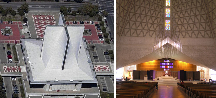
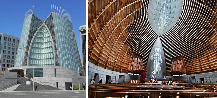
What approaches best suit the building elements in the below buildings?
St. Marys Catherdral - Nervi Architects
St Mary's Cathedral.3dm

Cathedral of Christ the Light - SOM

In Class Exercise
This exercises practices basic 3d modeling skills by creating three abstract "double negative" spaces using three methods: solid modeling, lofted surfaces and sweep surfaces. This exercise will be done at your desks in groups of two.
Please save your files here as .3dm with both student names listed.
Model a Double Negative Space in 3 ways
Demonstration: Stairs and Ramps
This demonstration will look at how the above methods can be used to construct 3d stairs and ramps on the Point Bonita site, revealing the pros and cons inherent to each method when applied to the same task.
If you have an idea about which method would work better for stairs or ramps, it's a good sign that you comprehend how to implement each method effectively.