| Workshop 1c | |
|---|---|
| Course | Arch 200c |
| Date | 2014/09/18 |
| Learning Objectives | The third workshop on graphic projection using 2d AutoCAD. This workshop covers the production of oblique and perspective views of three-dimensional scenes using two-dimensional processes. |
| Agenda |
|
| Uses Tool(s) | |
ACAD III: Non-Orthogonal Views
Prior to starting this workshop, please review our discussion of graphic projection .
We will begin the class by discussing and learning how to distinguish between different types of parallel projection drawings, other than the plan, section, and elevation. These are the oblique and axonomic drawings.
Understanding and Making Paraline Drawings
All paraline drawings are used to display three dimensional space in a way that is closer to reality than a perspective. They all have some truth to their dimensions, but exactly what is true differs from type to type. The drawing types are axonometric drawings ( isometric , dimetric , and trimetric ) and oblique drawings ( plan oblique , elevation oblique , and section oblique ). First we will learn what these drawings are and how to distinguish them from one another and then we will learn how to draw them.
Learning to Tell Axonometrics from Obliques
In Oblique Projections , an object is projected onto the viewing plane at a non-orthogonal angle. Projection rays are parallel to one another, but not perpendicular to the viewing plane. This is done with a bias so that certain elements of the drawing (either the plan or elevation/section) remain true, and thus can be measured.
In Axonometric Projections , an object is rotated along one or more of its axes relative to the plane of projection. Projection rays are parallel to one another, and perpendicular to the image plane - but in no specific relationship to any dominant plane of the object depicted.
There are three types of Axonometric Projections , which correspond to the angles used to project the drawing:
- Isometric projection
- Uses equal angles of 120º and is the most commonly used form of axonometric projection because of its ease of use with a 30º-60º triangle and clear representation. There is equal foreshortening on all sides (80% of the true size) and thus the plans and elevations cannot be used as base drawings.
- Dimetric projection
- Has equal foreshortening along two axis directions often emphasizing the elevation.
- Trimetric projection
- This technique is less common as all three axes planes are foreshortened and all axis angles are different.
Learning to Draw Axonometrics and Obliques
Computer drawing is often a way to make hand drawing easier, more precise, and faster. As such, learning how to use computers to make traditional representations in an almost one-to-one (that is, using the computer as a drafting board) has a lot of value, specifically learning what the drawings are supposed to look like, so you will know if your computer isn't doing what you want it to do.
In service of this, Francis D.K. Ching's books are an invaluable reference for all things drawing, even though he doesn't delve too far into the world of computers. We will use some explanation from his book before making our own oblique drawings.
Please follow this link to a workflow on how to create a plan oblique using 2D AutoCAD.
Understanding and Drawing a One-, Two-, or Three-Point Perspective
There are examples below of all three types of perspectives. Two-Point is probably the most common type of perspective drawing. While it closely imitates how we see, we do not actually see using two-point perspective.
Are all of these images perspectives? If so, how many 'points' do they have?


Discussion and activity to make a two-point perspective in AutoCAD
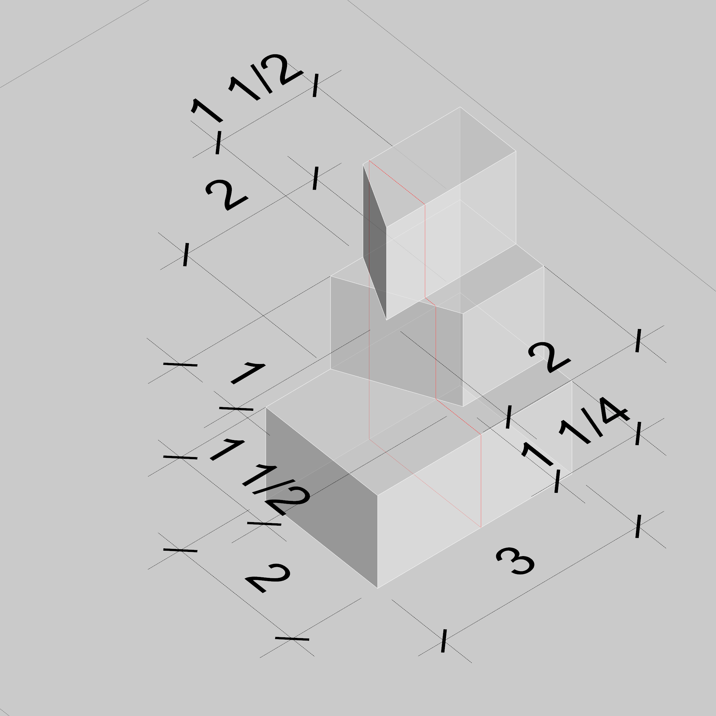
We will be almost exactly following this workflow , with a few small, but very important changes in order to create a perspective view of this object. You should have already completed plans and elevations for a previous exercise.

You can also find the plans for the object
here
Related
- Axonometric Drawings
- A detailed page with further information on axonometric drawing types and techniques.
- 1 Point Perspectives
- A detailed page with information regarding a one-point perspective by hand. This is very applicable to drawing a one-point perspective with 2D AutoCAD
- 2 Point Perspectives
- A detailed page with information regarding a two-point perspective by hand. This is very applicable to drawing a two-point perspective with 2D AutoCAD
- Analogous 2013 Session
- The above content roughly corresponds with this class session from last year.
- 2013 Session on Axons
- Check out last year's page on drawing axonometric projections.
- Create a Custom Perspectival Underlay in Rhino
- Demonstrates the creation of a custom persectival underlay aligned with a 3d view in Rhino
In-Class Exercise

We will be drawing the above object in multiple different ways today. Using only 2D AutoCAD, first, construct either a plan or elevation oblique drawing, and then construct a two-point perspective of it. For the obliques, use a 30 degree projection. For the perspective, please assume the viewpoint is .75" above the bottom of the object.
The base file including both plans and one elevation can be found here .
