| Week 4 - Rendering with Vray | |
|---|---|
| Course | Arch 124A |
| Date | 2012/10/16 |
| Learning Objectives | This workshop will introduce VRay as a tool for rendering. The underpinnings of this rendering software, including settings and material selection/creation will enable you to create specific and variable images of your Rhino3d models. The goals here will not be to create "finished products" directly from VRay, but rather to help you generate a "base" image that will be further refined, edited and contextualized in Photoshop and possibly Illustrator. |
| Agenda |
|
| Uses Tool(s) | VRay , Rhinoceros |
Introduction to VRay
VRay is a photorealistic render engine plug-in for a variety of 3d modeling programs, including Rhino. While it is an extremely powerful rendering engine with globla illumination, irradiance maps, and raytracing, it's also a complicated one. There are many different variable settings that can change how your rendering comes out and it will take many rounds of trial and error to get exactly what you want out of the renderer. This may be time-prohibitive, especially when you are just beginning to use VRay. Our goal is to use the software as a set-up of lighting, shadow, and perspective, then take the result into Photoshop or another photo editing program to get finer details.
For inspiration, take a look at The Third & The Seventh . They make entirely rendered films to show the power of digital rendering.
Interface
The toolbar for VRay consists of the following buttons (listed from left to right):
![]()
- Material Editor
- Create, edit, and assign materials to objects.
- VRay Options
- Edit VRay settings and load preset settings. Options shown here include settings for Camera, Output (image), Environment, Displacement, and Indirect or Global Illumination.
- VRay Frame Buffer
- Open rendering window.
- Add Sunlighting System
- Create a system based on physically based daylight, or set it to a specific location and time.
- Add Infinite Plane
- Creates an infinite plane along the XY plane at the Z zero location, creating a horizon.
- About VRay
- Information about VRay
Materials & Layers
There are two ways to access the Material Editor in V-Ray: from the toolbar and from the Object Properties panel. Using the V-Ray toolbar, left click on the icon that looks like a tag with the letter "M" on it. Or, select the object(s) to create a V-Ray material for. Use the Properties command and select Material from the drop-down menu. Assign by Plug-in and then click Create.
Creating Materials
Open the Material Editor in V-Ray. Right click on Scene Materials and select "AddVrayMtl."


Assigning Materials
Materials can be attributed to both layers as well as individual objects by using the Material Editor. Materials can be made up of different layer attributes (such as texture, transparency, bumps, etc) in effort to not read more than a flat texture mapping. Sometimes these layers depend on a value (such as intensity or a percentage of transparency) while other times they come from a gray-scale image.
You can quickly view what these materials look like by changing the view to Rendered View which offers a simplified version of the texture maps on the object. However many of the details will change once you actually render the image so it is important to test render throughout the process to check your work.
The next step is to attribute the material to objects or layers. Materials can be applied in two ways: from within the V-Ray Material Editor, or within an object's Properties in Rhino.
In the V-Ray Material editor, right click on the material name, and then click on either "Apply material to layer(s)" or "Apply material to object(s)".

To attribute the material to objects or layers in Rhino, select the objects or layers. Then, use the Properties command and select Material from the drop-down menu. Assign the material by Plug-in, and then click Browse to select the desired material (in the case of this workflow, the material is called Screen1).

Editing VRay Layers
Each VRay Material consists of the following:
Diffuse Layers
- Diffuse Color
- Change the overall color of an object OR texture map an image onto the an object by selecting the "m" box.
- Transparency
- Change the overall transparency of an object OR map a transparency pattern onto the object. Black is completely opaque and white is completely transparent.
Emissive Layers
- Emissive
- Changes the object to become an emitter. Change the intensity to affect how bright the light source becomes. Can change color, intensity, and transparency.

Reflection Layers
- Reflection
- Adds reflection to the object. White is completely reflective (like a mirror) and black is non-reflective. By Default the reflection layer has a fresnel map which varies the amount of reflection based on the viewing angle (notice the capital M next to the Reflection layer). To make more reflective, increase the Fresnel IOR.
Refraction Layers
- Transparency
- The darker the Refraction Transparency, the more the material references the edges of the objection (although transparent).
- Fog Color
- Use this rather than Refraction Color to change the color of the transparent material. Fog color is dependent upon the multiplier, the color and the size of the object. Be sure to pick a color that is slightly less saturated that you desire.
- Glossiness
- Helps change the frostiness of the transparent material. The lower the number, the more blurry the refraction.
- IOR (Index of Refraction)
- Essentially the degree to which the angle of light entering the material changes upon exiting the material. Calculated the light refracted from the tranparent object. Lowering the IOR decreases the intensity of the Refraction settings.

Maps
- Bump Map
- Changes the way the surface texture appears three-dimensionally, changes the surface normal to create the illusion of surface detail.
- Displacement Map
- Actually changes the way the surface appears three-dimensionally (such as outlines and edges of the surface) to represent a textured surface
Cameras
When setting up your rendered views in Rhino, you want to think about how the camera is being used to helpfully depict your scene, for whatever purposes. You may wish to focus on circulation and get a close up of the stairs and passages into a space, or you may be interested in a sequence of spatial experiences as you move through a space or series of spaces. Regardless of your focus, a healthy understanding of how to set up your camera shots will be imperative in helping you reveal these various conditions clearly.
Saving Views
- Saved Views
- In Rhino, you can save views so that you'll be able to come back to them at any point later on, even if you've shifted your view around in any of the viewports. Right click on each viewport title and you'll see a drop down menu; go to Set View and click on Named Views.... Here you'll be able to save your current view in the currently selected viewport and give it a name.
- Orient Camera to Surface
- The OrientCameratoSrf command allows you to set up a surface for the camera to lock on. This can be very helpful when setting up exact views, such as axonometrics.
Controlling Views
- Setting up Views
- Eye level - this should be approximately 5 feet above the ground plane
- Birds Eye - this view if from above, looking down at the overall context of the site and the design.
- Interior view (looking out from library) - similar to the bird-eye view, this view is specific to the Potrero Library project because it's a familiar view. When creating this view, consider how a window or interior scene might frame the final viewpoint
Saved Views
As you should know by now, by clicking View>Set View>Named Views, you can Save your Camera View and access it again later. You may find that much of your model is not needed for the particular render your putting together. To save file space, you can delete the superfluous geometry and re-save the file as the render name or whatever you like. Below is an example of when a particular shot requires only a piece of the whole model.
(Left: Saved View, Right: Simplified Model (200C, 2011):

Walkabout
If you make a 5' tall vertical surface off of the ground plane and OrientCameraToSrf, your camera will be 5' off the C-Plane. From here, if you type Walkabout your z-axis height locks, but you can zoom in an out along the 5' tall plane, as if you were walking around in 3d space. You can tell you're in WalkAbout mode by a small cross-hair in the middle of the screen, shown in the image below. To exit WalkAbout mode, type it again.

With WalkAbout turned on, you can also look around or "LookAbout", though that's not a command. Without zooming, you simple orbit around and the point you are at will be held, while the rotation around that point will be adjusted, like you were looking around without moving.
View Camera / Set Camera
To properly set you camera, you'll probably want to see where it is in 3d space. This is viewport specific, fyi. By simply typing "Camera", you can show the camera in the viewport you are in. The camera will show up in the other viewports, so make sure you open all 4 viewports to accurately see the camera.
For example, if I type Camera>Show, and I'm in the perspective Viewport (shown below), the camera will appear in all three other viewports, exposing how it's framing the perspective viewport. If I type Show for another viewport, like Front View, the same thing will happen, and the other three viewports will pick up that camera scene.

- Lens Length
- The perspective camera in Rhino is set to 50 mm by default, replicated the approximate amount of perspective we see in real life. Look at this value in the Properties menu. As the value increases, the lines of perspective become more parallel. As the value decreases, the lines of perspective increase which could be helpful for an interior view. See examples below.
-
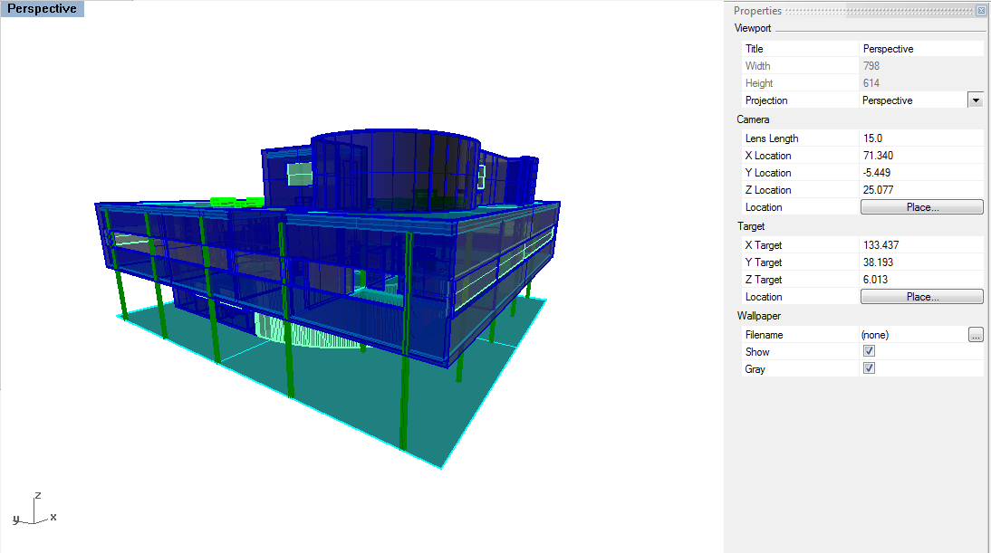
Lens Length at 15 - extreme perspective
-
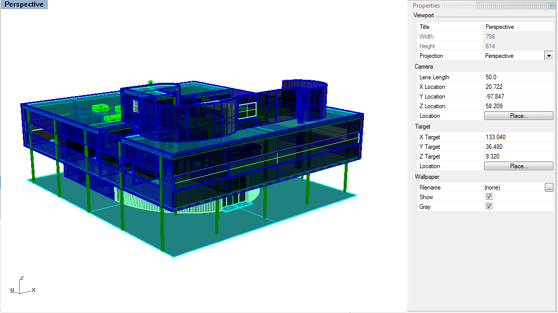
Lens Length at 50 - default
-
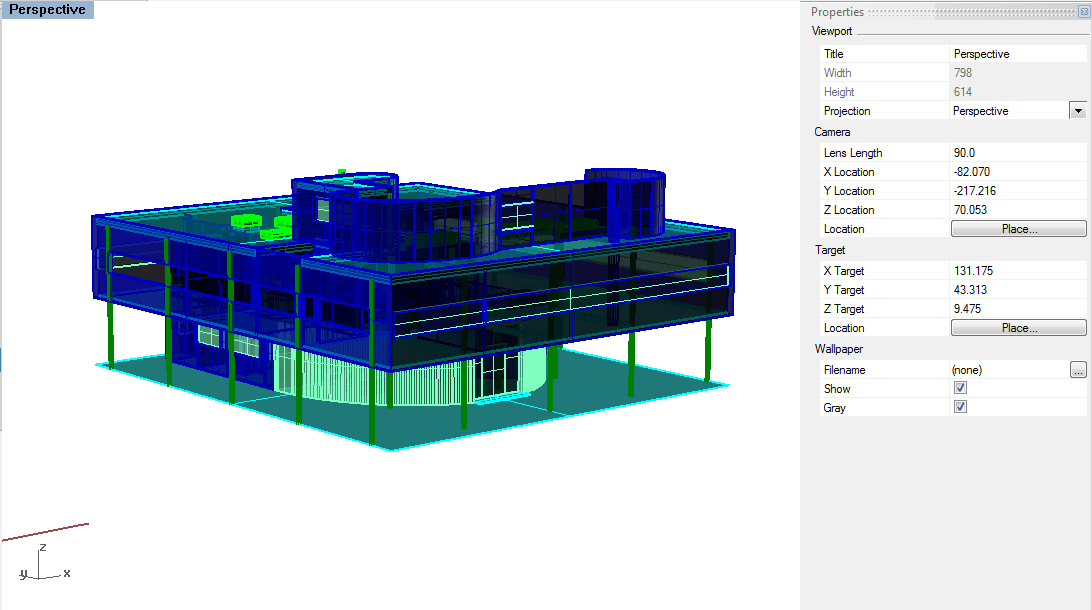
Lens Length at 90 - less perspective, close to Parallel view


Basics of Lighting
Lighting plays the most important role in rendering because it affects the color, shadow, reflection, and refraction among objects and materials in the scene. V-Ray comes equipped with Global Illumination , which is the natural lighting in a scene. It can be difficult to produce a specific lighting effect because of the many ways to create lights, as well as to change a light's appearance in a final render.
Be sure to choose a light that's best for the type of lighting needed for the scene. Lights can be created using Rhino commands. Or, use the sun and sky tool that is built into V-Ray to position a directional light.
There are two main ways to change lighting options. The first way uses the Properties panel in Rhino to change the properties of a selected light. This is helpful for controlling specific light objects. The second way uses Light Options in V-Ray, which controls the ambient light in the scene--that is, the lighting for the entire scene, not just one specific light.
Settings for all lights are controlled in V-Ray Options.
Environment
- GI (Skylight)
- This controls the Global Illumination . A V-Ray Sky can be added for illumination.
- Background
- This controls the color of the background in the render. It can be changed to an image by clicking on the m next to the color selection.
Typically, exterior renderings can quickly be made by using the default GI. However, to light a scene specific to a time and day, the sun and sky can be set. Interior renderings require a different set of lights. There are several different types of lights in Rhino , but only a few are especially helpful for rendering interior scenes .
Sunlight System


The Sunlight System, when partnered with the Physical Camera settings and various options within Vray, give the user a great range of flexibility in creating accurate daylighting renderings for 3d models. First off click the Sunlight System button at the V-Ray menu to bring up the dialogue box. Here you have the option to manually position the sun with horizontal and vertical angles (be sure to keep the sun above the horizon or you will not get illumination). You can also choose a specific location and specific time if you want to place the rendering within your given site.
You can also adjust the settings of the sunlight by selecting the light within the rhino screen. Once selected input properties or click the object properties tab in the tools menu. This will bring up the Object Properties Dialogue Box, here click on the drop down menu and select Light under object. This box gives you the option to re-position the light with the modify button. Below this there are other buttons that effect the way the sun performs in the renderings.
Turbidity, when the value is raised increases the atmospheric haze creating a smoggy effect, and a warmer color cast (3 default - 6-12 warm - 20 heavily altered) Ozone, when raised gives a blue cast to the scene (0.35 default - 1.0 blue cast) Intensity Multiplier, when raised the sun's strength becomes stronger (levels depends on camera settings) Size Multiplier, when raised creates softer shadows (1 default - 6 soft shadows -12+ very soft shadows)

Creating Composite Materials
Color can be added to a material by simply selecting a color for Diffuse. However, to make your renders look convincing, you'll often want to employ a specific material to a surface. Just using a color for the material will render too flat and even. To add some texture and irregularity to the color of the material, an image map should be used. In order to do this, I wouldn't always take the time to make a new material from scratch, since V-Ray comes pre-loaded with sample materials that often are only in need of updating for nice results. However, if the material you want isn't there, you can create materials from scratch, which we are going to do with some concrete.
Use these files to follow along:
Rendered Room.3dm
Concrete Image.jpg
Concrete Image_bw.jpg
Image Mapping
To start, you'll need to make an image to map onto a surface, simply called an "image map". You'll need to find an image of concrete. Not any image, but a nice image for tiling, without overly distinguishing areas that will be noticable in the tiling. These sites have some good selections for various material image maps:
- CGTextures
- Vast library of high-resolution textures for download. Account registration required.
- Maya NG's Textures
- Over 4250 free, high-resolution textures. Limited to 20 downloads per day.
I've selected this image:

Once you have your image, you need to apply it to a material in V-Ray. You do this by opening the V-Ray material editor, right clicking on "Scene Materials", selecting Add Material, and then clicking "Add VRay Mtl". Make sure to rename your new material by giving it a name that matches the material, such as "Concrete".

If you click the grey "Diffuse" layer, you'll notice a small "M". By clicking it, you'll open a new menu box that will allow you to apply your image map. Select "Bitmap" on the left menu and then upload the image and click "Apply". You can update for a preview of the change.

Once you have the image mapped, apply the material to a layer or surface. The result should look like this:

Adjusting the Scale
Depending on the scale of the model, the way the model was built, and the default settings in V-Ray, the image map and transparency map may not be rendered in V-Ray accurate to the scale of the building in real life. The image map may be enlarged and look stretched out, or the transparency map may not create the right effect because of its size relative to the building.
The test render should reveal whether or not the image map and transparency map are mapping at the right scale.
To change the scale of the perforations, edit the UVW of the transparency map in the Material Editor, under UVW Transform. In the Repeat column, increase the values of U and V to increase the number of times the image map repeats within each surface. Click on the Update button to preview the material texture.

Changing both the U and V repeat setting to 8 should work for this room, but you'll have to adjust for different sized models. Offsetting the tiling can help avoid seams jumping out, but if you want lines to match up, it won't help. It's safe to use when you don't have a lot of straight lines in your image map. I'm not using here.
Once the scale is adjusted, the image should come out like this:

Though the scale is right, the image is flat and lacks texture.
Texture Mapping
In order to add some depth to the material, we can add a bump map or a displacement map. These work like image maps, but add texture instead of an image. You'll need another version of your file that is black and white only,where white represents the part of the image you want to "pop out" slightly. Doing this in photoshop is easy.
A big difference between bump maps and displacement maps is that bump maps do not affect shadows, while diplacement maps actually alter the geometry for the render, and therefore affect shadows in the final output. They are set up in the same way. For this workshop, let's use the displacement map. Follow the same steps as the Image Map, including the UVW Transform scale changes, only add the new black and white concrete image as the Bitmap. Hit Apply.

Your image should now come out like this:


The color here is yellowish, so with some small changes in the VRay options, including updating the white balance, and changing the primary rendering engine to "Irradiance Map", we get a better color balance.

For more on editing VRay options, including skies and more camera settings, you should visit this helpful page: VRay 1.5 for Rhino
Transparency Mapping
Though we won't get into it here, there are also Transparency Maps, which you can check out here:
Transparency Maps - VRay
Rendering vs. Photoshop
The purpose of renders and perspective drawings is to make help the viewer understand the spatial qualities of the design. Sometimes texture mapping using a rendering program can be really helpful in showing the realistic qualities of light and materality within a digital model - but there is also a potential for the texture mapping to flatten the space. Texture mapping every detail within the digital model can also become a quick time trap, both in the effort you contribute to create the materials, and the amount of time it takes for VRay to render.
Another way of texture mapping is in post processing : Photoshop. Trees and people are a great example of something that we typically do not 3d model but add later on in the image. Other examples may be other elements of context (signage, neighboring buildings) as well as complex materials (water, grass).
Associated Workflows
- Introduction to VRay
- This workshop will introduce VRay as a tool for rendering. The underpinnings of this rendering software, including settings and material selection/creation will enable you to create specific and variable images of your Rhino3d models. The goals here will not be to create "finished products" directly from VRay, but rather to help you generate a "base" image that will be further refined, edited and contextualized in Photoshop and possibly Illustrator.
- Vray 1.5 for Rhino
- Many options for polishing your renders in VRay, including how to use HDRI skies, VFB channels, ISO and Shutter speed settings and more.
- Best Practices in VRay Rendering
- VRay is a powerful tool for rendering realistic scenes from a 3D model. Generally, a model is built, a point of view is chosen, the scene is rendered, and the resulting image is edited. This workflow will show the basics of rendering in VRay, including render settings, material selection, and texture mapping.
- Creating Composite Materials Using Image-Maps in VRay
- Using the facade of the de Young Museum as an example, this workflow demonstrates how to use custom-generated image maps to define composite material "layers" in V-Ray. Using the material editor dialog, we will edit the transparency, diffuse, and displacement layers to create the pattern of punches across the material, alter the color using an image map, and simulate the bumps of the material.
- Creating various rendering effects with VRay
- This workflow shows how to use Vray for Rhino to create various rendering outputs, using the Sunlight System and the numerous options with the Render Options Dialogue box and the Light Properties Dialogue box.
- Rendering with Hidden Geometry in Rhino & VRay
- This workflow shows a simple method for rendering 3d models to show cut sections or plans while maintaining true lighting. We will utilize specific tools in Rhino to split our model, than create transparent materials in VRay to "hide" our cut-away model while leaving its ability to block light.
Resources
- VRay for Rhino Manual
- The official manual for VRay
- Render Textures
- A great collection of texture map ensembles. Each material consists of different matching material maps (such as diffuse, bump, displacement, transparency). This is a good place to go if you want to create your own material from scratch.
- Flying Architecture
- VRay for Rhino Materials] : This website has some good materials for free download, such as concrete, wood and glass. Be sure to save the whole unzipped folder in an easy to find location.