| Week 4 – 3d Site Modeling | |
|---|---|
| Course | Arch 100a |
| Date | 2012/09/21 |
| Learning Objectives | Learning objectives: This class will focus on 3d modeling and drawing the site and its context. Students will learn how to export and import work into Rhino and other programs to develop a group site model. Importing, exporting, scaling and collection of site context will be reviewed. |
| Agenda |
|
| Uses Tool(s) | Rhinoceros |
Exercise 03 Review + Double Negative Review Review
- Standard lineweight hierarchy is important but it's impoortant to stand back from your drawing and make sure it "reads" okay. Use your best judgement in the end.
- Take photographs of your model and save your final drawings on your backup hard-drive
Site Plan Precedents
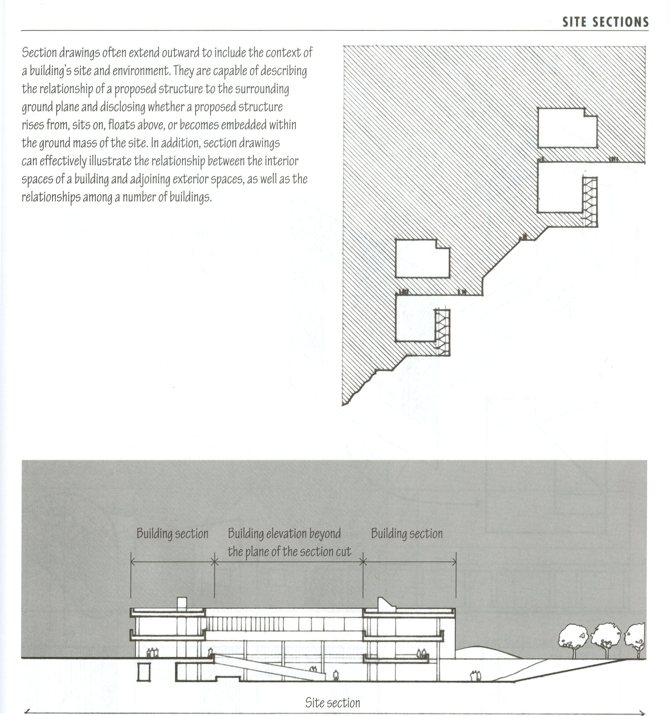
The drawings below are all copied from Francis Ching "Architectural Graphics."
Site Plans
In general, site plans and sections cater to many of the same conventions we use in typical plan / section drawing: the closer the object, the thicker the lineweight. Detailed elements such as trees and sidewalks also become lighter.
Site plans are typically drawn as if from overhead with the roofs of the building like the examples to the left. Some prefer the building (the proposed design) to be cut through the first floor like the buildings in the Nolli plan, to show movement through the building in relationship to the site. Sometimes shadows are overlaid on top to help the viewer understand the relationship between the ground plane and the height of the building. This could be easily rendered using Rhino Render in the top view if the building and site are modeled. Contour lines are also there to represent the topology of the site. Each line represents a 5' or 10' change in elevation (usually noted in the drawing).
Site Section
Site sections are sections cut through the site, including the neighboring buildings and the ground plane. These are often represented by a single line that continues through both the ground and through the building. Sometimes the building itself is given a poche to show the outline of the basement or foundation. If cutting through water, the section line would continue underneath the water as well - like along the bottom of lake or river, while another poche would show the height of the water
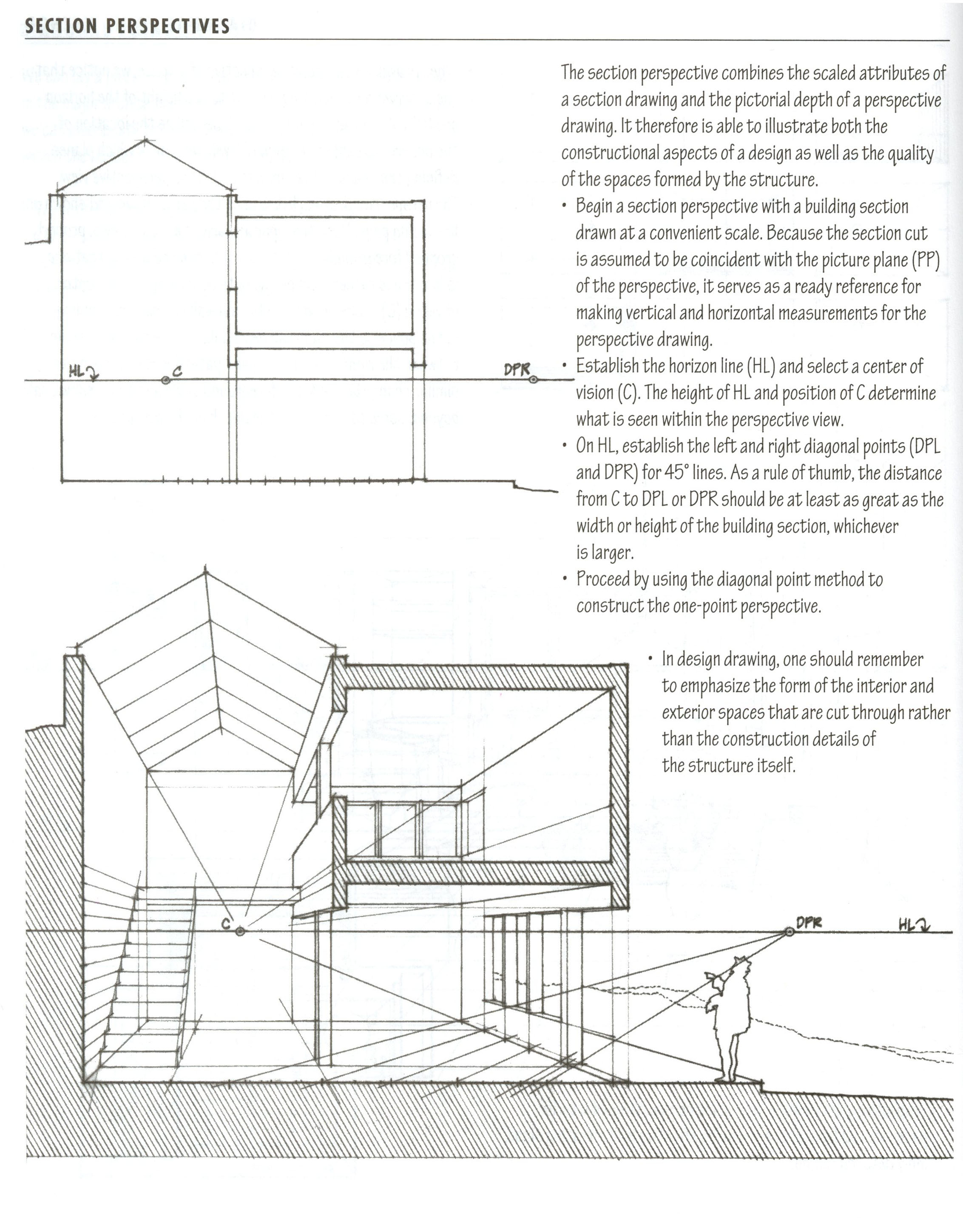
Section Perspective
Another helpful drawing type to consider in representing the site would be a section perspective. This would be a section through the site but viewed in Perspective . This way, some context of the depth of the site would be shown in the drawing. We will be practicing this type of drawing later in the semester when we produce a section perspective drawing of your building.
Site Modeling
There are two ways to think about modeling the site:
- Modeling the site accurately as it exists physically for purposes of site drawings or renderings.
- Modeling the site for purposes of analysis drawings (using precise information to inform the modeling tools used).
- Helpful Surface Commands + Modeling Tools
- Scale and precision are important when modeling the site, therefor we will be reviewing the following commands as we review some 3d modeling tools. Many of these tools will be used in the following workflow.
- Units - incredibly important to check when working on site data. Check Options to verify which units you are working in
- Distance - to measure the length of an object or line. The length should show up in your command line according to your units
- Scale , Scale1d , Scale2d - to rescale your objects
- BackgroundBitmap - places a background image in the current viewport for tracing. Locks the object in place, must refer back to BackgroundBitmap command for scaling, rotating and removing the image.
-
PictureFrame
- More flexible than BackgroundBitmap but similar. Sets the image as the texture map so the image appears as an object that can easily be selected, scaled, rotated, etc. Image appears in every viewport.
- PictureFrame not working? Change the object display mode with the command SetObjectDisplayMode and change to "Rendered".
-
Extrude
- Creates a surface that is extruded from an existing linework
- ExtrudeAlongCurve - Uses a line as the extrusion vector
- ExtrudeTapered - Extrudes at a specified angle
- ExtrudeToPoint - Extrudes to a specific point
- PlanarSrf - Creates a planar surface within a closed curve
- EdgeSrf - Creates a surface between 2,3, or 4 edges
- Patch - Creates a surface along a series of lofted curves such as lifted topographical contour lines. See the workflow below for additional details.
- Digitally Modeling the Site
- This workflow describes the steps necessary to develop a 3d model and drawing of the site. Students will learn how to export and import data from/into rhino, scale to accurately reflect site data, collect and draw site information, organize layers and responsibilities to develop a 3D group site model and drawings.
WORKFLOW + EXERCISE
- Workflow - Drawing Site Sections from a Digital Model
- This workflow will overview the Section and Make2d commands to create a site section drawing. Additional Illustrator tools will be added as well such as fills, background image and entourage will be added to create a finished drawing.
- Exercise - Site Sections
- This week's exercise asks you to use the existing site model to draw sections through the site. Some of this will overview previous skills learned such as the Section command and Make2d before importing the data into Illustrator.
This file should be printed out at 11" x 17" and turned into a bin on the 6th + 7th floor elevator lobby (right outside of studio). Your name and your GSI's name should be located on the lower right hand corner of this print out.
All final submissions are due no later than 5:00 pm on Friday, September 21st.
Additional Illustrator Tools
The following includes a list of tools that can be helpful for creating generic analysis or diagrammatic drawings in Illustrator:
- Clipping Masks - Frames objects by a clipping mask or closed object that rests on top. Helpful for combining images and linework together.
- Live Trace - Transforms a raster image into a vector image. Helpful for making quick silhouettes or linework for laser cuttings.
- Live Paint - Transforms linework to a Live Paint groups where you can drop in fills and strokes into all visibly "closed" lines.
- Blend Tool - Transforms one object to another in a series of specified steps. Works for curves and fills.
Also - download this
example Entourage Template
which includes hundreds of silhouettes of peoples, cars and trees.
Additional Workflows
Having Difficulty with modeling or drawing the site? Check out some of these workflows that use many of the same tools that we will be reviewing in class:
- Modeling Topographic Surfaces
- Using site contours, this workflow show how to use the Patch command to create a surface represented the topography of the site.
- Creating Contextual Building Elevations
- This video workflow show how to detail surrounding buildings with windows and elevation elements to make the scene more site specific rather than generic cubes. This would prove helpful when creating street elevations and renderings your final design.
- Drawing a Site Plan
- Follow this workflow if you want to trace more information into the site plan using satellite images of the site.
- Drawing Figure Ground Site Plan
- This workflow emphasizes tracing historic site plans or importing site data to create simple figure ground drawings.


