| Week 04 - Site Representation and Analysis | |
|---|---|
| Course | Arch 100a |
| Date | 2013/09/20 |
| Learning Objectives | This class will introduce methods of site representation and analysis. Students will learn tools for digital site modeling as well as different analytical approaches to diagramming and representing the site. |
| Agenda |
|
| Uses Tool(s) | Rhinoceros , Illustrator CS5 |
Methods of Site Representation
Last week we learned methods for creating analytical drawings of your Double Negatives in axonometric projection and were introduced to some tools useful for translating models from digital to physical. This week we’ll carry many of those concepts forward into issues of site representation.
Site can be represented in a number of ways. More conventional standards of site representation rely on orthographic drawing types such as Plan , Section and Elevation . Increasingly, digital site models are used as a means for consolidating and organizing all the relevant site information. These sophisticated files can contain an abundance of data. However, when considering the site in terms of your design approach, it can be useful and important to study the site with a specific lens; examining just a specific set of conditions and distilling the site information. These studies are represented in analytical site drawings.
Today we will be discussing the various types of site representation and reviewing a number of helpful tools for working through these different methods.
An Overview of Site Drawing Types
In general, site plans and sections cater to many of the same conventions we use in typical plan / section drawing: the closer the object, the thicker the lineweight. Detailed elements such as trees and sidewalks also become lighter.
The drawings below are all copied from Francis Ching "Architectural Graphics."
Site Plans
Site plans are typically drawn as if from overhead with the roofs of the building like the examples to the left. These drawings illustrate the relationship of the building to its surrounding context. Neighboring buildings are typically depicted, especially in urban sites, as well as any surrounding landscape conditions. Sometimes shadows are overlaid on top to help the viewer understand the relationship between the ground plane and the height of the building. This could be easily rendered using Rhino Render in the top view if the building and site are modeled. In sites with more sloped terrain contour lines represent the topography of the site. Each line represents a 5' or 10' change in elevation (usually noted in the drawing).
Figure-Ground Site Plan
Figure-Ground Site plans are often used in urban sites to show the density of lot occupation and the relationship of built space to open space. The most well-known of this drawing type, the Nolli map , cut through the first floor to show movement through the building in relationship to the site - his drawing focused specifically on the public realm so only the publicly accessible parts of buildings were depicted with the rest of the buildings left solid poche.
Site Section
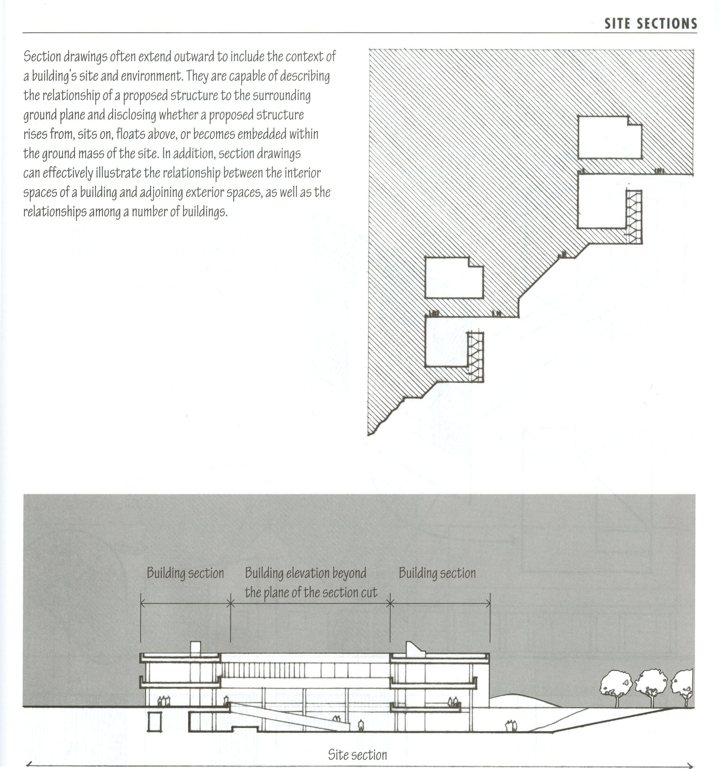
Site sections are sections cut through the site, including the neighboring buildings and the ground plane. These are often represented by a single line that continues through both the ground and through the building. Sometimes the building itself is given a poche to show the outline of the basement or foundation. If cutting through water, the section line would continue underneath the water as well - like along the bottom of lake or river, while another poche would show the height of the water
Section Perspective
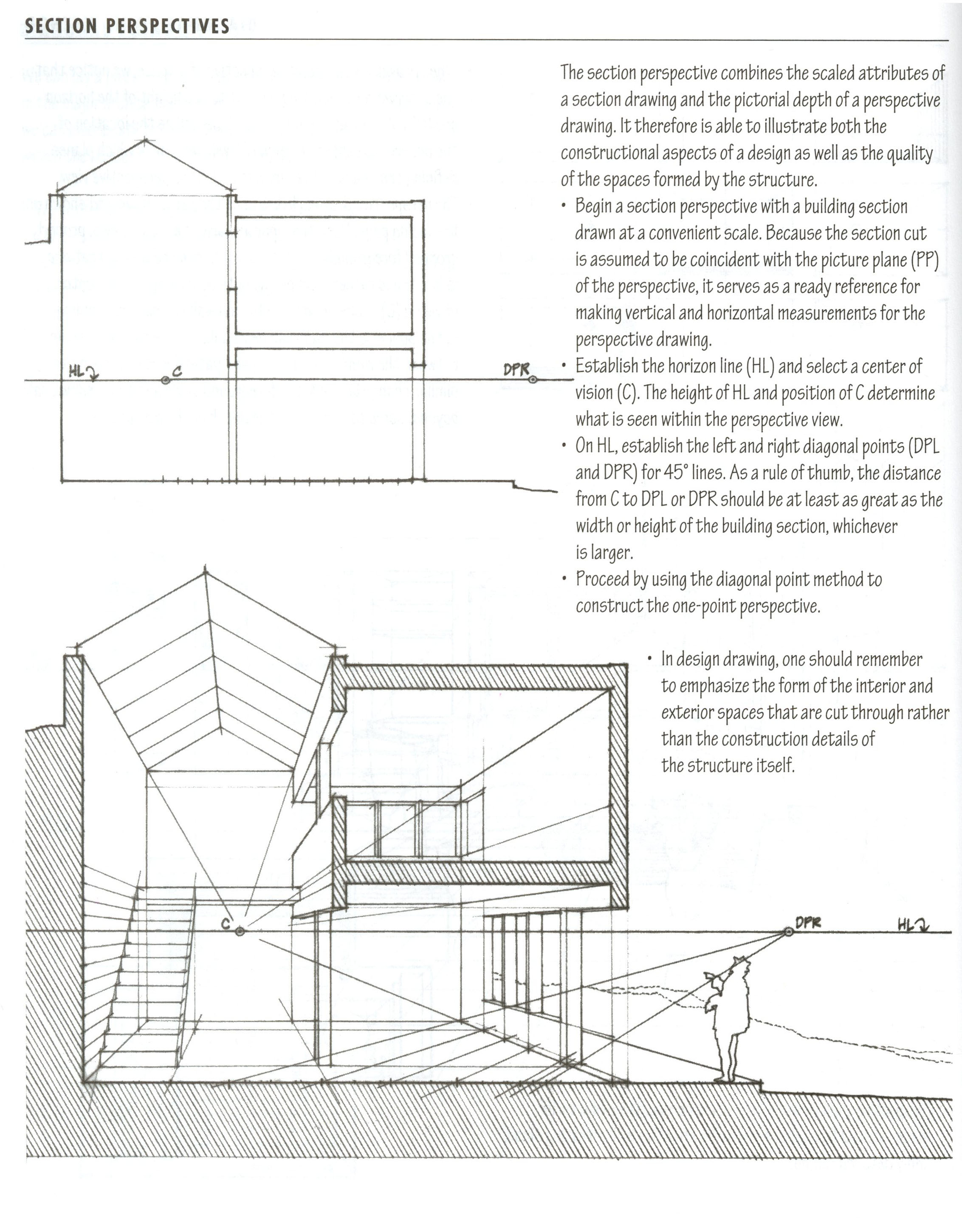
Another helpful drawing type to consider in representing the site would be a section perspective. This would be a section through the site but viewed in Perspective . This way, some context of the depth of the site would be shown in the drawing.
We will be practicing this type of drawing later in the semester when we produce a section perspective drawing of your building. But for a sneak peek, here is a workflow that details steps for Cutting a Section Perspective through your Digital Model
Techniques for Digital Site Modeling
Digital Site Models allow for a dynamic consolidation of site information into a single file. These models are extremely useful but like all digital models, require thoughtful, intentioned working methods to ensure that the model is used as an effective tool.
Potrero Hill Site Model
A digital model of the Potrero Hill site can be downloaded here
- Though a digital site model is provided, it should be noted that this is a very simple massing model and should NOT be taken as-is. As you consider the site and work through your analyses, you should be building in additional information to suit your site studies.
Working within the Digital Model
Given the density of information in most site models, conscientious work practices are extremely important to keep your model clean and under control. It's best to always save an archive copy of the digital model before making any significant changes.
- While many of the tools listed below have been introduced before, they are especially relevant to digital site modeling and worth re-mentioning.
Getting Started//Setting up the Model
- Units - incredibly important to check when working on site data. Check Options to verify which units you are working in
- Distance - to measure the length of an object or line. The length should show up in your command line according to your units
- Scale , Scale1d , Scale2d - to rescale your objects
- BackgroundBitmap - places a background image in the current viewport for tracing. Locks the object in place, must refer back to BackgroundBitmap command for scaling, rotating and removing the image.
-
PictureFrame
- More flexible than BackgroundBitmap but similar. Sets the image as the texture map so the image appears as an object that can easily be selected, scaled, rotated, etc. Image appears in every viewport.
- PictureFrame not working? Change the object display mode with the command SetObjectDisplayMode and change to "Rendered".
- CPlanes - short for Construction Plane, defines the working surface of the drawing elements. When "Planar" is selected in Rhino, all new linework or geometry will snap to the CPlane. CPlanes can be manually set and saved which is helpful when working with irregular geometry or topography.
Editing Existing Geometry
- Split - Breaks up objects along cutting planes, lines, or points.
- Trim - Simultaneously splits and deletes unwanted geometry.
- Explode - All-purpose command for breaking stuff apart. Using it recursively on the same set of objects may produce different results - for example, explode preformed on a group containing polycurves will first dissolve the group, and then break apart the polycurves into their constitute curves.
-
Move
- Translates an object from one place to another. Check out the use last distance and use last point options for producing arrays of objects easily.
- MoveEdge - By clicking a specific edge in a polysurface, you can pull and push it to a new position and the poly-surface will rebuild itself to accomodate the change.
- MoveFace - Extrudes a poly-surface along just one face.
- Cap - Fills missing planar faces in a poly-surface.
Creating New Forms
- Extrude - Creates a surface that is extruded from an existing linework.
- Project - Projects geometry onto selected surfaces, polysurfaces or meshes. Very useful when working within topographic sites.
- PlanarSrf - Creates a planar surface within a closed curve
- EdgeSrf - Creates a surface between 2,3, or 4 edges
- Patch - Creates a surface along a series of lofted curves such as lifted topographical contour lines. See the workflow below on Modeling Topography for additional details.
Techniques for Site Analysis
For our site studies into the Potrero Hill site, we will be looking primarily at morphological and formal conditions, rather than more ephemeral qualities (ie physical and spatial aspects of the site instead of street activity). For the richest site investigations, consider and compare a few different criteria in order to discover relationships and reveal a more nuanced view of the site.
These drawings will likely be the result of working through a number of different mediums, be it photography from the site visit, data from the site model or satellite maps, and Illustrator linework or Photoshop image editing.
Analytical drawings and diagrams try to take a situation and distill it down to a simple idea, one that doesn't take long to "get" right away. As is the case with all abstractions, they present a selected, edited, and redacted version of the world. Though these drawings will be abstracted and distilled, they must still be precise and represent an accurate (though pointedly curated) view of the site. You are applying your own lens to the site, but it shouldn't distort it.
Useful Software Tools
Illustrator
- Clipping Masks - Frames objects by a clipping mask or closed object that rests on top. Helpful for combining images and linework together.
- Image Trace - Transforms a raster image into a vector image. Helpful for making quick silhouettes or linework for laser cuttings. (Formerly known as Live Trace)
- Blend Tool - Transforms one object to another in a series of specified steps. Works for curves and fills.
- You can test out these different tools with this illustrator file
Rhino
- Contour - Useful for quick serial site sections. Set contour distance at scale of study; ie Block scale (aprox. 200') , Lot Scale (aprox. 25'), etc.
- Make2D - Extract linework for additional editing in Illustrator
- Export - Export linework at scale
Additional Site Data Resources
While nothing can match a site visit in person, there are many resources that can provide supplemental information when examining or representing your site. Though many of these sources contain somewhat redundant information, it is often helpful to consult both - sometimes a truck is blocking your street view; an aerial view shows outdated site information, etc.
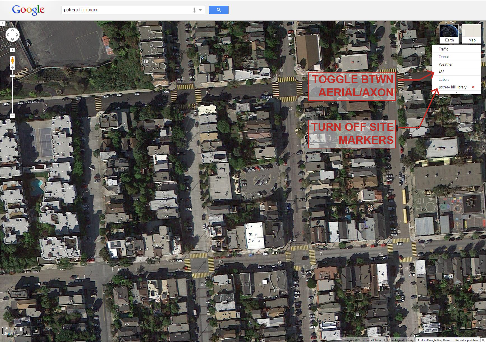
- If using aerial images as an underlay or base for diagramming, it is good practice to turn off any labels or text that Google or Bing may provide. [intent, your own interpretation, considered source material, not just lazy, etc]
Some useful resources for additional site data:
- Google Maps - One of the most popular sources for aerial image, Google Maps provides both satellite as well as their "45-degree" view which roughly mimics an axonometric aerial view. Street views can also be found for most streets in larger cities.
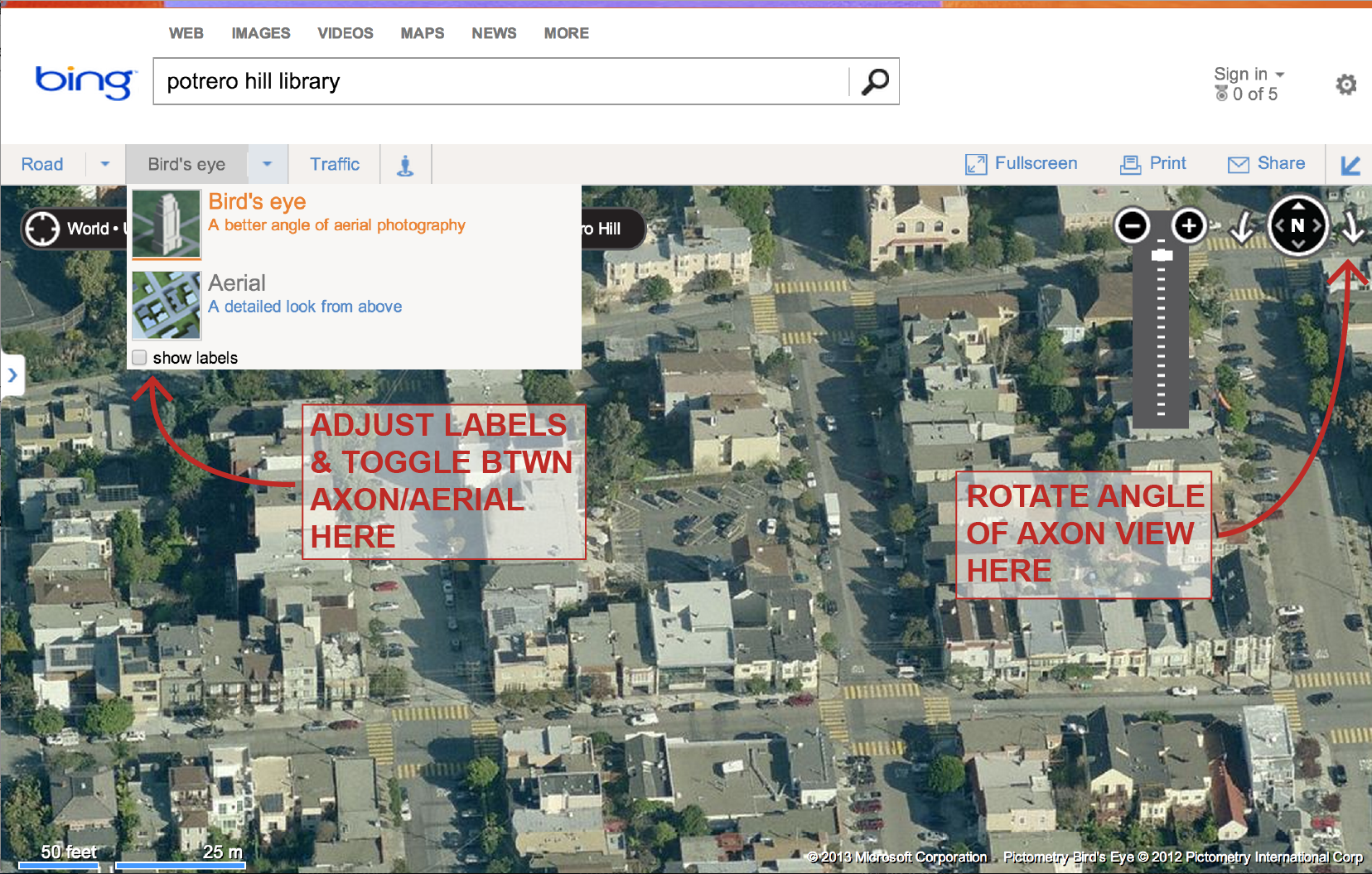
- Bing Maps - Bing contains much of the same information as Google, however their "Bird's Eye View" feature (like Google's 45-degree view) can also be rotated for alternate views. This feature is extremely useful when trying to determine more detailed information about facades or roof lines, etc. Like Google, Bing Maps also has a street view function. A simple screenshot is typically the easiest way to export desired views.
-
Sanborn Maps
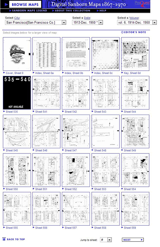
- Historical (and mostly current) map collection used for estimating fire insurance liability. Information is limited, but can be useful for determining lot lines and building extents. Some land use information is included on occasion. You will need to consult the Key Sheet to determine which map volumes and sheets are relevant to your project.
- Proxy Server will be needed for connection to the collection off-campus.
- Hint - Potrero Hill is Vol. 6 in the collection
Additional Workflows
Having difficulty with modeling or drawing the site? Check out some of these workflows that use many of the same tools we discussed in this session:
- Digitally Modeling the Site
- This workflow describes the steps necessary to develop a 3d model and drawing of the site. Students will learn how to export and import data from/into rhino, scale to accurately reflect site data, collect and draw site information, organize layers and responsibilities to develop a 3D group site model and drawings.
- Drawing Site Sections from a Digital Model
- This workflow will overview the Section and Make2d commands to create a site section drawing. Additional Illustrator tools will be added as well such as fills, background image and entourage will be added to create a finished drawing.
- Modeling Topographic Surfaces
- Using site contours, this workflow show how to use the Patch command to create a surface represented the topography of the site.
- Creating Contextual Building Elevations
- This video workflow show how to detail surrounding buildings with windows and elevation elements to make the scene more site specific rather than generic cubes. This would prove helpful when creating street elevations and renderings your final design.
- Drawing a Site Plan
- Follow this workflow if you want to trace more information into the site plan using satellite images of the site.
- Drawing Figure Ground Site Plan
- This workflow emphasizes tracing historic site plans or importing site data to create simple figure ground drawings.


